Switching circuitry
Once the Arduino has decided between the RES and the battery, the switching circuitry in the project overview connects the chosen supply to the pump. An Arduino pin can supply only about 20 mA at 5 V; a pump needs amps at 12 V or more. The switching circuitry lets the small signal control the large current.
This chapter covers two ways of doing it: the relay module used on the breadboard prototype, and the MOSFET switches on the RenewableSwitchOver board.
Learning outcomes
By the end of this chapter you should be able to:
- Explain how a relay module works and wire a load through it
- Drive relays from the Arduino, including active-LOW modules
- Build and program the RES / battery switch-over with relays
- Read the RenewableSwitchOver schematic and explain how its MOSFET switches, driver transistors and diodes work
- Compare relays and MOSFETs for switching the supply
1. What the switching circuitry must do
- Connect one supply to the pump. The pump’s positive supply comes from either the RES or the battery.
- Never connect the two supplies together. If the RES and the battery were joined directly, current would flow from the higher one into the lower one, limited only by wiring resistance.
- Isolate the Arduino from the power circuit. The Arduino provides a logic-level signal and nothing more.
2. The relay module

A 5 V dual relay module has two independent relays on one board, each controlled by an Arduino digital pin. It contains opto-isolators: the Arduino’s signal drives an LED inside the opto-isolator, which switches the relay driver. The Arduino is therefore optically (not electrically) connected to the relay coil, which protects it from the coil’s voltage spikes.
Control side vs operating side

| Side | Pins | Connects to |
|---|---|---|
| Control (low-voltage) side | VCC, GND, IN1, IN2 |
Arduino 5 V, GND and two digital pins |
| Operating (switched) side | Screw terminals for each relay: NC, COM, NO |
The power circuit being switched (RES, battery, pump) |
The relay contacts on these modules are rated up to 10 A at 250 VAC / 30 VDC, far beyond anything an Arduino pin could switch directly.

The jumper between JD-VCC and VCC lets the relay coils share the Arduino’s 5 V supply; leave it in place.
The relay mechanism
Inside each relay is an electromagnet (coil) and a switch arm:
| Terminal | Meaning |
|---|---|
| COM | Common — the moving contact; wire your power source here |
| NC | Normally Closed — connected to COM when the relay is off (coil not energised) |
| NO | Normally Open — connected to COM only when the relay is on (coil energised) |
| Relay off (de-energised): COM → NC | Relay on (energised): COM → NO |
|---|---|
 |
 |
When the coil is energised, its magnetic field pulls the arm from NC across to NO: you hear a click and the module’s indicator LED lights.
Switching a load
To switch a lamp (or pump, or LED) from a battery:
- Battery +ve → COM
- NO → load → ground (battery −ve)
The lamp then lights only when the relay is energised. Wire to NC instead if you want the load on by default and switched off by the Arduino.
 |
 |
⚠️ Active-LOW inputs. On most of these blue opto-isolated modules a LOW on
IN1/IN2turns the relay ON, and HIGH turns it off. Test yours: upload Example 3a and watch which state lights the module LED.
🔧 Try it: Relay simulator — switch between active-LOW and active-HIGH and between NO/NC wiring.
3. Driving the relays from the Arduino
Example 3a — open and close relay 1

| Arduino | Relay module |
|---|---|
| 5 V | VCC |
| GND | GND |
| Pin 13 | IN1 |
⚠️ The diagram above labels the supply wire “3.5V to vcc”. The Arduino has no 3.5 V pin, and the relay coils are rated at 5 V: connect VCC to the 5 V pin.
/*
 * Example 3a: Switch relay 1 on and off every second.
 * Hardware: Arduino 5 V -> VCC, GND -> GND, D13 -> IN1 on the relay module.
 */

const uint8_t  kRelay1Pin = 13;      // Arduino pin 13 drives IN1
const uint16_t kSwitchMs  = 1000;    // time in each state (ms)

// The relay module is active-LOW: LOW switches a relay on, HIGH switches it off.
const uint8_t  kRelayOn   = LOW;
const uint8_t  kRelayOff  = HIGH;

void setup() {
  digitalWrite(kRelay1Pin, kRelayOff);   // choose "off" before the pin becomes an output
  pinMode(kRelay1Pin, OUTPUT);
}

void loop() {
  digitalWrite(kRelay1Pin, kRelayOn);    // relay energised: COM connects to NO (click)
  delay(kSwitchMs);
  digitalWrite(kRelay1Pin, kRelayOff);   // relay released: COM back to NC (click)
  delay(kSwitchMs);
}
kRelayOn = LOWandkRelayOff = HIGHgive names to the module’s back-to-front logic. If you swap to an active-HIGH module you only change these two lines.digitalWritebeforepinMode: at start-up the pins are inputs. WritingHIGHfirst and then making the pin an output means it goes straight to “off”. The other way round briefly outputsLOW, which would click the relay on for an instant at every reset.
▶️ Run it: Example 3a in the code runner — watch
kRelayOn(LOW) switch the relay on.
Exercise 3b — alternate relay 1 and relay 2

Add pin 12 → IN2.
/*
 * Exercise 3b: Alternate between relay 1 and relay 2.
 * Hardware: D13 -> IN1, D12 -> IN2, 5 V -> VCC, GND -> GND.
 */

const uint8_t  kRelay1Pin = 13;      // drives IN1
const uint8_t  kRelay2Pin = 12;      // drives IN2
const uint16_t kRelay1Ms  = 500;     // time with relay 1 on (ms)
const uint16_t kRelay2Ms  = 1000;    // time with relay 2 on (ms)
const uint8_t  kRelayOn   = LOW;     // active-LOW module
const uint8_t  kRelayOff  = HIGH;

void setup() {
  digitalWrite(kRelay1Pin, kRelayOff);   // both relays off at start-up
  digitalWrite(kRelay2Pin, kRelayOff);
  pinMode(kRelay1Pin, OUTPUT);
  pinMode(kRelay2Pin, OUTPUT);
}

void loop() {
  digitalWrite(kRelay2Pin, kRelayOff);   // relay 2 off first ...
  digitalWrite(kRelay1Pin, kRelayOn);    // ... then relay 1 on
  delay(kRelay1Ms);

  digitalWrite(kRelay1Pin, kRelayOff);   // relay 1 off first ...
  digitalWrite(kRelay2Pin, kRelayOn);    // ... then relay 2 on
  delay(kRelay2Ms);
}
Off before on (break before make): each change switches the old relay off before switching the new one on. With LEDs it makes no difference, but when the relays switch the RES and the battery, it stops the two supplies ever being connected together, even for a moment.
▶️ Run it: Exercise 3b in the code runner — see each relay switched off before the other comes on.
Exercises 3c and 3d — switch LEDs through the relays

- A separate battery powers an LED circuit; its +ve goes to COM of relay 1, and NO → resistor → blue LED → battery −ve. The Example 3a code now switches the LED, but the LED’s power comes from the battery, not the Arduino.
- Wire a green LED through relay 2 the same way and run the Exercise 3b code: the LEDs alternate as the relays alternate.

Exercise 3e — potentiometer control

This combines Read input voltage with the relays: the pot chooses which relay is on.
/*
 * Exercise 3e: The potentiometer chooses which relay is on.
 * Below 2.5 V: relay 2 on (green LED). At or above 2.5 V: relay 1 on (blue LED).
 * Hardware: pot wiper -> A1; D13 -> IN1 (blue LED circuit);
 *           D12 -> IN2 (green LED circuit); 5 V -> VCC, GND -> GND.
 */

const uint8_t  kPotPin     = A1;
const uint8_t  kBlueRelay  = 13;      // IN1: switches the blue LED
const uint8_t  kGreenRelay = 12;      // IN2: switches the green LED
const float    kThreshold  = 2.5;     // switching voltage (V)
const float    kAdcVref    = 5.0;
const float    kAdcMax     = 1023.0;
const uint16_t kSampleMs   = 100;
const uint8_t  kRelayOn    = LOW;     // active-LOW module
const uint8_t  kRelayOff   = HIGH;

float readVolts(uint8_t pin) {
  return analogRead(pin) * (kAdcVref / kAdcMax);
}

// Switch a relay on (true) or off (false), hiding the active-LOW detail.
void setRelay(uint8_t pin, bool on) {
  digitalWrite(pin, on ? kRelayOn : kRelayOff);
}

void setup() {
  Serial.begin(9600);
  digitalWrite(kBlueRelay, kRelayOff);    // both off at start-up
  digitalWrite(kGreenRelay, kRelayOff);
  pinMode(kBlueRelay, OUTPUT);
  pinMode(kGreenRelay, OUTPUT);
}

void loop() {
  float vOut = readVolts(kPotPin);
  Serial.println(vOut);

  if (vOut < kThreshold) {
    setRelay(kBlueRelay, false);          // off first ...
    setRelay(kGreenRelay, true);          // ... then on: green LED lit
  } else {
    setRelay(kGreenRelay, false);
    setRelay(kBlueRelay, true);           // blue LED lit
  }

  delay(kSampleMs);
}
Replace the pot with the divider from the RES and the LEDs with the RES and battery supplies, and you have the switch-over system.
▶️ Run it: Exercise 3e in the code runner — move the pot either side of 2.5 V and follow
setRelay().
4. The switch-over with relays
The breadboard prototype builds the whole system with the relay module. A resistor and LED stand in for the pump.
Building it

Power and signals from the Arduino to the relay module: 5 V → VCC, GND → GND, pin 13 → IN1 (battery relay), pin 12 → IN2 (RES relay).
RES power in through its relay: RES +ve → COM of the RES relay; its NO → the breadboard rail that feeds the load; RES −ve → the ground rail.

Step 2: +ve RES into a relay COM terminal, −ve RES to the breadboard Battery power in through its relay: battery +ve → COM of the battery relay; its NO joins the same load rail; battery −ve → the ground rail.

Step 3: +ve battery into the other relay’s COM, −ve battery to ground The monitoring system: the voltage divider across the RES, with its mid-point to an analogue input (see Voltage regulation).

Monitoring voltage divider from the RES to the Arduino analogue pin All the grounds connected together: RES −ve, battery −ve, Arduino GND and the load’s −ve on one rail. Without a shared ground,
analogReadhas no reference.
Don’t forget to ground: Arduino GND to the breadboard ground rail
| Connection | From | To |
|---|---|---|
| Relay power | Arduino 5 V | Relay VCC |
| Relay ground | Arduino GND | Relay GND |
| Battery relay control | Arduino pin 13 | IN1 |
| RES relay control | Arduino pin 12 | IN2 |
| RES supply | RES +ve | COM, RES relay |
| Battery supply | Battery +ve | COM, battery relay |
| Load supply | NO of both relays | Load (+) |
| Common ground | RES −ve, battery −ve, Arduino GND, load (−) | Breadboard ground rail |
| Monitoring | RES +ve → R₁ → (A0) → R₂ → ground | Arduino A0 |
The code
/*
 * Run the load from the renewable energy source (RES) while its voltage is
 * high enough, and switch to the battery when it drops.
 * Hardware: divider mid-point -> A0; D12 -> IN2 (RES relay);
 *           D13 -> IN1 (battery relay); 5 V -> VCC; all grounds joined.
 */

const uint8_t  kResPin     = A0;       // divider mid-point
const uint8_t  kResRelay   = 12;       // IN2: connects the RES to the load
const uint8_t  kBatRelay   = 13;       // IN1: connects the battery to the load
const float    kThresholdV = 2.5;      // below this (at the pin) the RES is too low
const float    kAdcVref    = 5.0;
const float    kAdcMax     = 1023.0;
const uint16_t kSampleMs   = 100;
const uint8_t  kRelayOn    = LOW;      // the relay module is active-LOW
const uint8_t  kRelayOff   = HIGH;

float readVolts(uint8_t pin) {
  return analogRead(pin) * (kAdcVref / kAdcMax);
}

// Power the load from the RES. The battery is disconnected first.
void useRes() {
  digitalWrite(kBatRelay, kRelayOff);
  digitalWrite(kResRelay, kRelayOn);
}

// Power the load from the battery. The RES is disconnected first.
void useBattery() {
  digitalWrite(kResRelay, kRelayOff);
  digitalWrite(kBatRelay, kRelayOn);
}

void setup() {
  Serial.begin(9600);
  digitalWrite(kResRelay, kRelayOff);    // both relays off until we decide
  digitalWrite(kBatRelay, kRelayOff);
  pinMode(kResRelay, OUTPUT);
  pinMode(kBatRelay, OUTPUT);
}

void loop() {
  float vPin = readVolts(kResPin);       // 1. read the RES voltage first ...
  Serial.println(vPin);

  if (vPin < kThresholdV) {              // 2. ... then decide
    useBattery();
  } else {
    useRes();
  }

  delay(kSampleMs);
}useRes()anduseBattery()each describe a whole action in one name, soloop()reads like the specification.- Off before on. Each function disconnects the old source before connecting the new one, so the RES and battery are never connected together.
- Read, then decide. Each decision uses the latest reading. Add the hysteresis from Read input voltage so the relays don’t chatter when the RES hovers near the threshold.
▶️ Run it: the switch-over sketch in the code runner — drag the A0 voltage below 2.5 V and watch the load move to the battery.
🔧 Try it: RES battery-backup simulator — vary the wind, the divider and the threshold, and watch the Arduino switch the load between the RES and the battery.
5. The RenewableSwitchOver board
The project board does the same job with no relays: each supply is switched by a P-channel MOSFET, turned on and off by an NPN transistor, and the two switched supplies are joined through diodes. The board also carries the voltage regulation divider and the L298N pump driver.
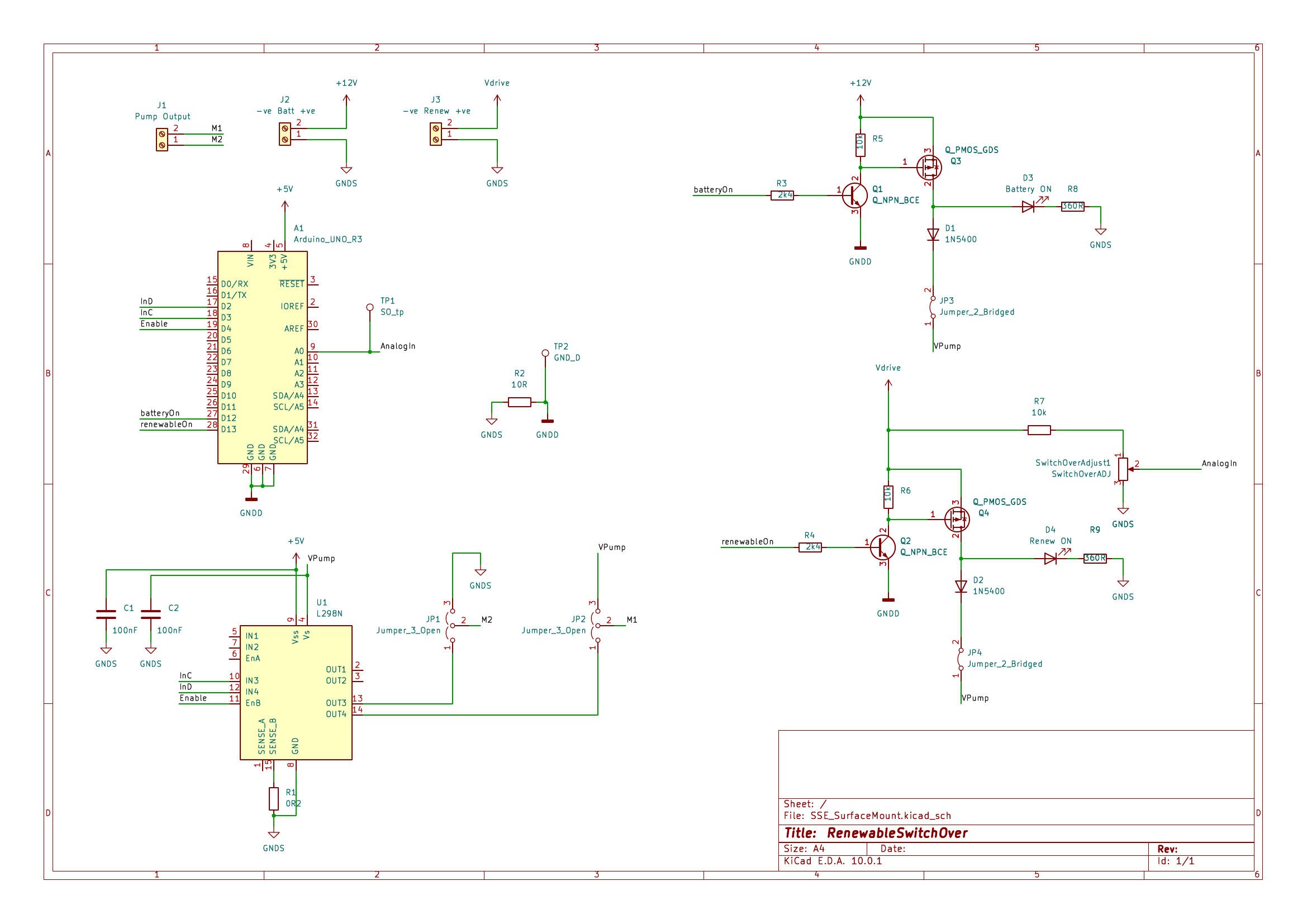
The Arduino’s connections
| Arduino pin | Net | Goes to | Chapter |
|---|---|---|---|
| A0 | AnalogIn | Wiper of the SwitchOverADJ trimmer; TP1 | Voltage regulation, Read input voltage |
| D12 | batteryOn | Q1 → Q3: switches the battery in | this chapter |
| D13 | renewableOn | Q2 → Q4: switches the RES in | this chapter |
| D3 (PWM) | InC | L298N IN3 | Pump drive type |
| D2 | InD | L298N IN4 | Pump drive type |
| D4 | Enable | L298N EnB | Pump drive type |
| 5 V, GND | +5V, GNDD | L298N logic supply; driver transistor emitters |
| Connector | What it is |
|---|---|
| J2 (Batt) | Battery: +ve to +12V, −ve to GNDS |
| J3 (Renew) | RES: +ve to Vdrive, −ve to GNDS |
| J1 (Pump Output) | Pump, terminals M1 and M2 |
The two supply switches are identical, so the description below follows the battery side (Q1, Q3, D1, D3); the RES side is Q2, Q4, D2, D4 with Vdrive in place of +12V.
High-side P-MOSFET switch: Q3
Q3 sits between the battery’s +12V and the pump supply, on the high side (the positive side). Switching the positive side means the pump’s negative and the supplies’ negatives stay permanently joined to ground, which keeps the shared ground the voltage measurement needs.
A P-channel MOSFET conducts from source to drain when its gate is pulled well below its source:
- Q3’s source is at +12 V. R5 (10 kΩ) pulls the gate up to +12 V too, so the gate–source voltage \(V_{GS} = 0\) and Q3 is off.
- To turn Q3 on, the gate must be pulled down towards 0 V, giving \(V_{GS} \approx -12\) V.
Why the NPN transistor: Q1
The Arduino cannot do that job itself. Its pin only reaches 5 V, so connected straight to the gate it would hold \(V_{GS}\) at about −7 V: Q3 could never turn off, and the 12 V on the gate would reach the Arduino pin. Q1 is a level shifter:
- batteryOn HIGH: current flows through R3 (2.4 kΩ) into Q1’s base: \(I_B \approx (5 - 0.7)/2400 \approx 1.8\) mA, well within the pin’s 20 mA. Q1 saturates and pulls Q3’s gate to almost 0 V. Q3 turns on.
- batteryOn LOW: no base current, Q1 is off, R5 pulls the gate back to +12 V. Q3 turns off.
Q1 only has to sink the current through R5: \((12 - 0.2)/10\,000 \approx 1.2\) mA. Both switches are active-HIGH: digitalWrite(12, HIGH) connects the battery, digitalWrite(13, HIGH) connects the RES.
⚠️ The gate voltage on the RES side follows the RES. With the RES at 16 V, Q4’s \(V_{GS}\) is about −16 V. Check the MOSFET’s maximum \(V_{GS}\) in its datasheet (±20 V is common). At a low RES voltage (a few volts) Q4 is only partly on, but by then the code should have switched to the battery anyway.
The diodes: D1 and D2
The drains of Q3 and Q4 feed the pump supply VPump through D1 and D2 (1N5400: 3 A, 50 V). The diodes form a diode-OR: VPump is fed by whichever switched-in supply is higher, and the other diode is reverse-biased.
They are there for two reasons:
- A MOSFET only blocks in one direction. Every MOSFET has a body diode from drain to source. Without D1, a 16 V RES on VPump would push current back through Q3’s body diode into the 12 V battery, even with Q3 off. D1 blocks it.
- Both supplies can be on at once safely. With relays, both on means the RES and battery are joined directly. With the diodes, current can only flow out of each supply towards the pump, never from one supply into the other.
The price is a forward voltage drop of roughly 0.8–1 V, which the pump never gets, and about \(P \approx 0.9\,\text{V} \times I\) of heat in the diode.
Indicator LEDs, jumpers and test points
- D3 “Battery ON” and D4 “Renew ON” light when their MOSFET is on, each through a 360 Ω resistor (R8, R9). At 12 V a red LED draws about \((12 - 2)/360 \approx 28\) mA, and with the RES at 16 V about 39 mA. Check that is within your LEDs’ rating; a larger resistor (e.g. 680 Ω) brings it nearer 15 mA.
- JP3 and JP4 (bridged) are in series with each supply’s diode. Cut or open one to isolate that supply, or to put an ammeter in the path.
- TP1 is A0 (set the trimmer here). TP2 is the Arduino’s ground.
Two grounds: GNDS and GNDD
The board has a supply ground, GNDS (battery −ve, RES −ve, pump, divider, L298N), and a digital ground, GNDD (the Arduino and the driver transistors’ emitters). They are joined at one point through R2 (10 Ω). The large pump current returns through GNDS without passing along the Arduino’s ground wiring, while the two grounds stay at the same potential for the A0 measurement.
Relays or MOSFETs?
| Relay module | MOSFET board | |
|---|---|---|
| Switching speed | About 10 ms, with contact bounce | Microseconds, no bounce |
| Wear | Mechanical: contacts wear and arc, especially under load | None |
| Noise | Clicks | Silent |
| Logic | Usually active-LOW | Active-HIGH |
| Voltage lost | Almost none across closed contacts | MOSFET on-resistance plus about 0.9 V across the diode |
| Isolation | Opto-isolators and contacts: no electrical connection to the Arduino | Shares a ground with the Arduino |
| AC or DC | Either | DC only |
| Both supplies on together | Short circuit between the supplies: always break before make | Safe, thanks to D1/D2: can make before break |
Code for the board
Because the diodes make it safe for both supplies to be on for a moment, the board can make before break: switch the new supply on before the old one goes off, so the pump never loses its supply during a switch-over.
/*
 * RenewableSwitchOver board: run the pump from the RES while it is high
 * enough, and switch to the battery when it drops, with hysteresis.
 * Pins from the schematic: A0 = AnalogIn (trimmer wiper),
 * D13 = renewableOn (Q2 -> Q4), D12 = batteryOn (Q1 -> Q3), both active-HIGH.
 */

const uint8_t  kSensePin   = A0;
const uint8_t  kResOnPin   = 13;      // renewableOn
const uint8_t  kBatOnPin   = 12;      // batteryOn
const float    kRatio      = 0.300;   // fraction of the RES voltage at A0, measured at TP1
const float    kToBatteryV = 8.0;     // RES volts: switch to the battery below this ...
const float    kToResV     = 9.0;     // ... and back to the RES only above this
const float    kAdcVref    = 5.0;
const float    kAdcMax     = 1023.0;
const uint16_t kSampleMs   = 100;

bool onBattery = false;

// The RES voltage, from the A0 reading and the measured divider fraction.
float readResVolts() {
  return analogRead(kSensePin) * (kAdcVref / kAdcMax) / kRatio;
}

// Make before break: the diodes D1/D2 stop the supplies feeding each other,
// so the new supply goes on first and the pump never loses power.
void useRes() {
  digitalWrite(kResOnPin, HIGH);
  digitalWrite(kBatOnPin, LOW);
  onBattery = false;
}

void useBattery() {
  digitalWrite(kBatOnPin, HIGH);
  digitalWrite(kResOnPin, LOW);
  onBattery = true;
}

void setup() {
  Serial.begin(9600);
  pinMode(kResOnPin, OUTPUT);
  pinMode(kBatOnPin, OUTPUT);
  if (readResVolts() < kToBatteryV) useBattery(); else useRes();
}

void loop() {
  float vRes = readResVolts();
  Serial.println(vRes);

  if (!onBattery && vRes < kToBatteryV) {
    useBattery();                     // RES clearly too low
  } else if (onBattery && vRes > kToResV) {
    useRes();                         // RES clearly recovered
  }

  delay(kSampleMs);
}- Measure
kRatioat TP1 as in Read input voltage. - Set the thresholds in RES volts from the pump’s minimum working voltage. 8 V and 9 V are placeholders.
- During reset the Arduino’s pins are inputs, so Q1 and Q2 get no base current and both supplies are off until
setup()runs. - This switches the supply only. Pump drive type adds the pump driver, and a slow start so the pump isn’t hit with a current surge every time the supply changes.
Key points
- An Arduino pin can’t switch a pump: the switching circuitry lets a 5 V, few-mA signal control amps at 12–16 V.
- Relay: COM is the moving contact; NC is connected when off; NO when on. The modules are usually active-LOW.
- With relays, always switch the old supply off before the new one on.
- On the board, each supply has a high-side P-MOSFET (Q3, Q4) driven through an NPN level shifter (Q1, Q2): D12 HIGH connects the battery, D13 HIGH connects the RES.
- Diodes D1/D2 block the MOSFETs’ body diodes and form a diode-OR, so both supplies can be on together safely, at the cost of about 0.9 V.