Project Overview
Introduction to microcontrollers
Over five chapters you build one working system: an Arduino that watches the voltage of a renewable energy source (RES), switches a pump over to a battery backup when the RES can no longer supply it, and starts the pump gently so the switch-over doesn’t cause a current surge. Each chapter covers one block of the diagram.
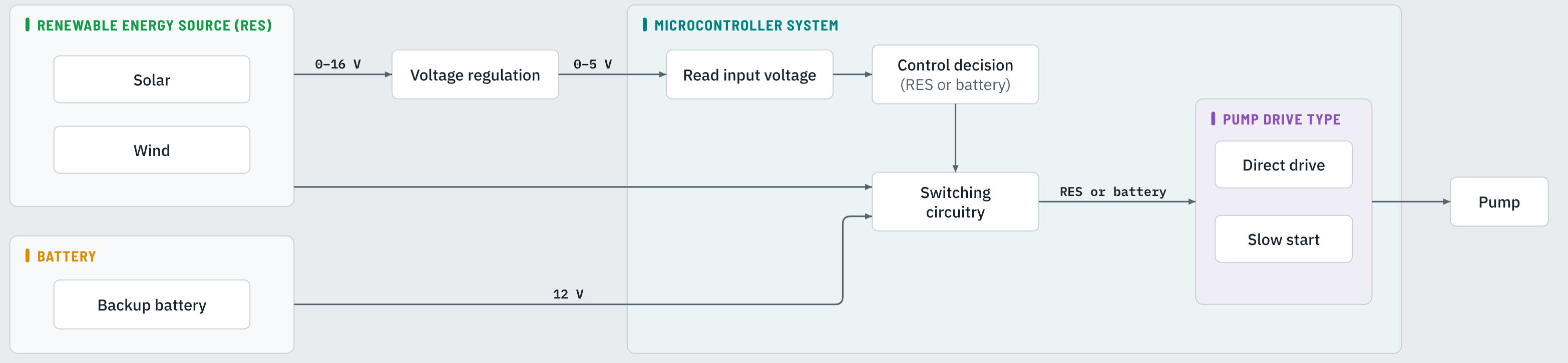
The chapters follow the diagram from left to right. Each block is summarised below, with a link to the chapter that covers it. The project is built on the RenewableSwitchOver board: its schematic is in Switching circuitry.
Renewable energy source (RES) and battery
Solar panels and a wind turbine supply the system. Their output changes with the sun and the wind, from 0 V up to about 16 V. A 12 V battery is the backup. Both connect to the board on screw terminals: the RES on J3, the battery on J2. Their negatives share one ground with the Arduino, so the RES voltage can be measured.
1 · Voltage regulation
The Arduino can only measure 0–5 V, so the RES voltage is scaled down in proportion by a voltage divider. On the board this is R7 (10 kΩ) and the SwitchOverADJ trimmer, whose wiper feeds A0. Set the trimmer at test point TP1 so the RES maximum gives just under 5 V.
Chapter 1: Voltage regulation: why the voltage must be scaled, the divider equation, choosing resistors, potentiometers, and setting the trimmer.
2 · The microcontroller system
An Arduino Uno reads the RES voltage, decides which supply to use, switches it in and drives the pump.
Chapter 2: Getting started with the Arduino: the board, the IDE, digital outputs, data types, loops and functions, and non-blocking timing.
3 · Read input voltage and the control decision
analogRead(A0) turns the scaled voltage into a number from 0 to 1023, which the code converts back to the RES voltage. An if/else threshold with hysteresis then decides: RES or battery.
Chapter 3: Read input voltage: analogRead, decisions with if/else, whole-number thresholds, recovering the RES voltage, and choosing the switch-over point.
4 · Switching circuitry
The chosen supply is switched to the pump. The breadboard prototype uses a relay module; the board uses a P-MOSFET for each supply (Q3, Q4), driven through an NPN transistor (Q1, Q2) from Arduino pins D12 (battery) and D13 (RES). Diodes D1 and D2 join the two switched supplies, so they can never feed each other.
Chapter 4: Switching circuitry: relays, the switch-over with relays, and the board’s MOSFET switches, diodes and code.
5 · Pump drive type
Jumpers JP1 and JP2 connect the pump either directly to the supply or through an L298N H-bridge (IN3 on D3, IN4 on D2, EnB on D4). Direct drive is simple but draws a large inrush current at every start and every switch-over to a higher supply. A slow start ramps the PWM up instead, which keeps the current low and the RES stable.
Chapter 5: Pump drive type: inrush current, direct drive, PWM, the L298N, and slow-start code, with the advantages and disadvantages of each.
Each chapter ends with a knowledge check, and the interactive applets let you try every circuit before you build it.