Voltage regulation
Chapter 1 · Introduction to microcontrollers
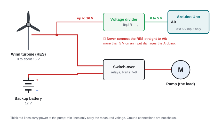
The first block after the renewable energy source (RES) in the project overview is voltage regulation. Its job is to bring the RES voltage, which can be anywhere from 0 V to about 16 V, into the 0–5 V range that an Arduino analogue input can safely measure. This chapter explains why that matters, how a voltage divider does it, and how the divider on the RenewableSwitchOver board is set up.
Learning outcomes
By the end of this chapter you should be able to:
- Explain why a varying source voltage must be scaled before an Arduino can measure it
- Tell the difference between scaling a voltage for measurement and regulating a supply for power
- Calculate the current and output voltage of a voltage divider
- Choose divider resistors from a source’s maximum voltage
- Use a potentiometer as an adjustable divider, and set the trimmer on the project board safely
1. Why the voltage has to be brought into range
The renewable source in the project is a solar panel and a wind turbine. Its voltage changes with the sun and the wind, from 0 V when everything is still up to about 16 V. The Arduino needs to know that voltage to decide whether the pump can run from the RES or must switch to the battery.
The problem is the Arduino’s analogue inputs:
- They measure 0 to 5 V only. Anything above 5 V reads as the maximum, 1023, so 6 V and 16 V look the same.
- Above about 5.5 V the input is outside the chip’s absolute maximum rating. The pin’s protection diodes start to conduct, and enough current through them damages the ATmega328P, sometimes the whole board.
- Below 0 V (a reversed source) is just as harmful.
So the RES must never be connected straight to an analogue pin. Something has to sit between them that turns 0–16 V into 0–5 V, in proportion, so the Arduino can still tell a weak source from a strong one.
Measuring is not the same as powering
“Voltage regulation” can mean two different things, and the project needs to keep them apart:
| Scaling for measurement | Regulating for power | |
|---|---|---|
| Purpose | Tell the Arduino how big the RES voltage is | Give a circuit a steady supply whatever the input does |
| Output | A fixed fraction of the input: it rises and falls with it | A constant voltage (e.g. 5 V) while the input is high enough |
| Typical part | Voltage divider (two resistors, or a potentiometer) | Linear regulator (e.g. 7805) or a switch-mode converter |
| Current it can supply | Almost none: microamps to a milliamp | Up to its rating (hundreds of mA or more) |
A regulator would be no use for monitoring: its output stays at 5 V whatever the RES does, so the Arduino would learn nothing. A divider is no use for powering anything: as soon as a load draws current from it, its output collapses. The Arduino Uno has its own 5 V linear regulator for its supply (7–12 V on the barrel jack or Vin); above about 12 V that regulator wastes \(P = (V_{in} - 5)\,I\) as heat. The voltage regulation block in the project is a measurement divider.
Using the whole range
The ADC divides 0–5 V into 1024 steps of about 4.9 mV. If the divider is designed so the RES maximum gives just under 5 V, the whole range is used and each step is as small as possible at the source. A divider that gives only 2.5 V at the RES maximum would throw half of those steps away.
2. Ohm’s law and resistors in series
\[V = IR\]
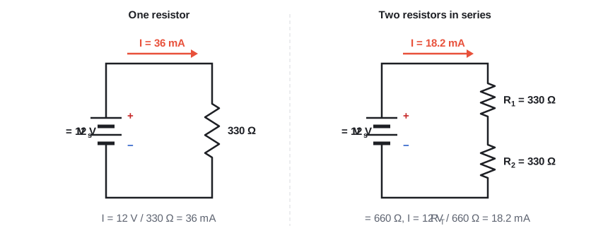
One resistor: \(V_s = 12\ \text{V}\), \(R = 330\ \Omega\), so \(I = \dfrac{12}{330} = 36\ \text{mA}\).
Two resistors in series: the resistances add, \(R_T = R_1 + R_2\). With \(R_1 = R_2 = 330\ \Omega\), \(R_T = 660\ \Omega\) and \(I = \dfrac{12}{660} = 18.2\ \text{mA}\): half the current, because there is twice the resistance.
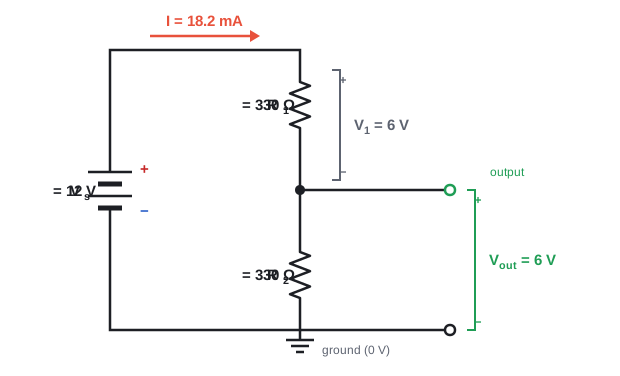
The voltage across each resistor is \(V = IR\) for that resistor: \(V_1 = (18.2\times10^{-3})(330) = 6\ \text{V}\), and the same across \(R_2\). The two add up to the 12 V supply.
3. The voltage divider
A voltage divider is two resistors in series across a supply, with an output taken from the point between them. Measured from ground (the bottom of \(R_2\)), that point sits at a fixed fraction of the supply voltage.
How it works, in three steps
- The same current flows through both resistors. There is only one path, so the current is set by the total resistance: \[I = \frac{V_s}{R_1 + R_2} = \frac{12\ \text{V}}{660\ \Omega} = 18.2\ \text{mA}\]
- Each resistor takes a share of the supply voltage, in proportion to its resistance. With the same current through both, \(V = IR\) means the bigger resistor drops the bigger voltage. Here they are equal, so each takes half: \(V_1 = V_2 = 6\ \text{V}\). The shares always add up to \(V_s\).
- The output is the voltage across \(R_2\). Substituting \(I\) from step 1 into \(V_{out} = I R_2\): \[\boxed{V_{out} = V_s\,\frac{R_2}{R_1 + R_2}}\]
An analogy: think of water flowing through a pipe with two narrow sections in a row. The same flow passes through both, and the pressure drops a little across each. The pressure between the two narrow sections depends only on how restrictive each one is compared with the other. In a divider, voltage plays the part of pressure, current the part of flow, and resistance the part of the narrow sections.
A worked example with unequal resistors
\(V_s = 9\ \text{V}\), \(R_1 = 330\ \Omega\), \(R_2 = 100\ \Omega\):
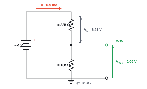
\[I = \frac{9}{430} = 20.9\ \text{mA}, \qquad V_{out} = 20.9\ \text{mA}\times100\ \Omega = 2.09\ \text{V}\]
⚠️ Always recalculate the current for each new pair of resistors. Reusing a current from an earlier example (say 20 mA) gives 2.0 V here, not 2.09 V. Keep full values until the last step.
The ratio is what matters
\(V_{out}\) depends only on the ratio of the resistors, not on their actual values:
| \(R_1 : R_2\) | Fraction \(\dfrac{R_2}{R_1+R_2}\) | \(V_{out}\) from 12 V |
|---|---|---|
| 1 : 1 | 1/2 | 6 V |
| 2 : 1 | 1/3 | 4 V |
| 1 : 2 | 2/3 | 8 V |
| 3 : 1 | 1/4 | 3 V |
- The total resistance sets the current, and so the power wasted as heat. 330 Ω + 330 Ω and 33 kΩ + 33 kΩ both give 6 V, but the second draws a hundred times less current. For a circuit that only measures a voltage, use large values.
- \(V_{out}\) is always between 0 and \(V_s\). A divider can only reduce a voltage, never increase it.
- Don’t draw current from the output. Anything connected to \(V_{out}\) takes some current and pulls the output down. An Arduino analogue input draws almost nothing, so a divider is ideal for measuring a voltage, and useless for powering a load.
The Analyse tab of the voltage divider lab (in Section 4) works out the current, output voltage, power and analogRead() value for any divider.
4. Choosing the resistors for the RES
Design from the maximum voltage the source can produce, and the voltage you want at the Arduino at that maximum (5 V). In this example the RES has a maximum voltage of 15.86 V:
\[5\ \text{V} = 15.86\ \text{V}\left(\frac{R_2}{R_1+R_2}\right)\]
\[5(R_1 + R_2) = 15.86\,R_2 \quad\Rightarrow\quad 5R_1 = 10.86\,R_2\]
\[\boxed{R_1 = 2.172\,R_2}\]
In general, for a maximum source voltage \(V_{max}\):
\[R_1 = \left(\frac{V_{max}}{5} - 1\right)R_2\]
Now choose a convenient \(R_2\) and calculate \(R_1\):
| \(R_2\) | \(R_1 = 2.172R_2\) | Nearest standard \(R_1\) | \(V_{out}\) at 15.86 V | Current |
|---|---|---|---|---|
| 1 kΩ | 2.172 kΩ | 2.2 kΩ | 4.96 V | 5.0 mA |
| 10 kΩ | 21.72 kΩ | 22 kΩ | 4.96 V | 0.50 mA |
| 100 kΩ | 217.2 kΩ | 220 kΩ | 4.96 V | 0.05 mA |
- Round \(R_1\) up to a standard value so that \(V_{out}\) stays just under 5 V.
- Larger resistances waste less energy, which matters in a sustainable system. But very large values (well over 10 kΩ in total) make the Arduino’s reading noisier, because the ADC needs a little current to charge its sampling capacitor. Around 10 kΩ for \(R_2\) is a good compromise.
- The result is only as accurate as the resistors: ±5 % parts give up to ±5 % error in the measured RES voltage. Measure the real values with a multimeter and use those in your code.
Try it: Voltage divider lab — the Scale tab takes your source’s maximum voltage and gives \(R_1\) as a multiple of \(R_2\), exactly as above; Analyse and Design check any divider. · Open full screen ↗
5. Designing for a set current
Sometimes you are given the output voltage and the current. Design a voltage divider with an output of 6 V and a current of 60 mA from a 12 V battery.
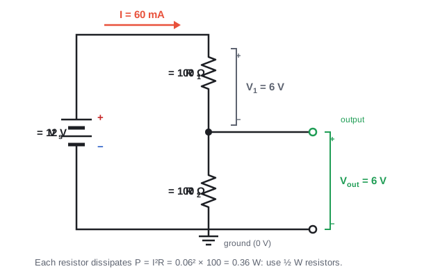
- Total resistance: \(R_T = \dfrac{V_s}{I} = \dfrac{12\ \text{V}}{0.06\ \text{A}} = 200\ \Omega\)
- \(V_{out}\) is the voltage across \(R_2\), so \(R_2 = \dfrac{V_{out}}{I} = \dfrac{6\ \text{V}}{0.06\ \text{A}} = 100\ \Omega\)
- \(R_1 = R_T - R_2 = 100\ \Omega\)
As a check: 6 V is half of 12 V, so the ratio must be 1 : 1, and it is.
⚠️ Watch the units: 60 mA is 0.06 A, not 0.06 mA.
Each 100 Ω resistor dissipates \(P = I^2R = 0.06^2\times100 = 0.36\ \text{W}\), more than a standard ¼ W resistor can handle. Use ½ W resistors, or larger values and a lower current. For measurement, the lower current is the better choice.
The Design tab of the voltage divider lab (in Section 4) reproduces this calculation for any \(V_s\), \(V_{out}\) and \(I\).
6. Potentiometers: an adjustable divider
A potentiometer (“pot”) is a voltage divider whose split you adjust by turning a knob. A small one adjusted with a screwdriver is called a trimmer.
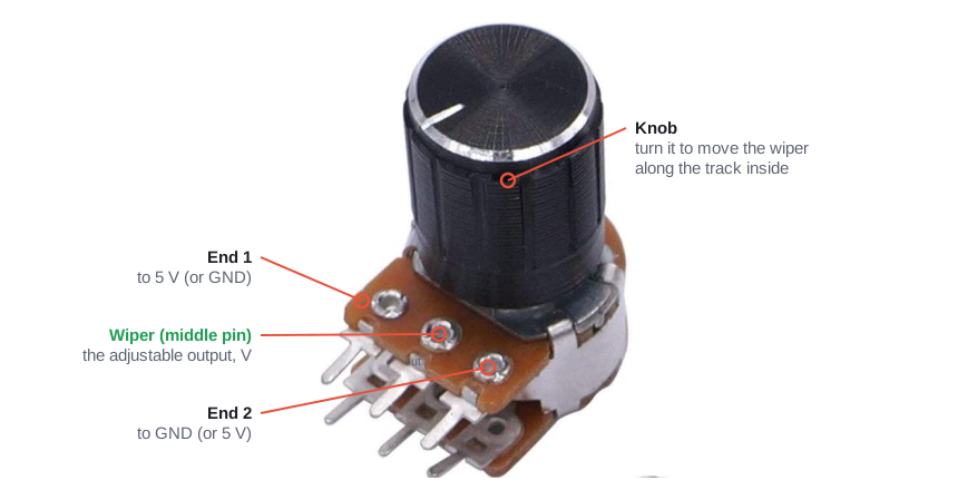
It has three pins. The two outer pins are the ends of a resistive track of fixed resistance (\(R_{tot}\), here 5 kΩ). The middle pin is the wiper, which touches the track and divides it into \(R_1\) (above the wiper) and \(R_2\) (below it):
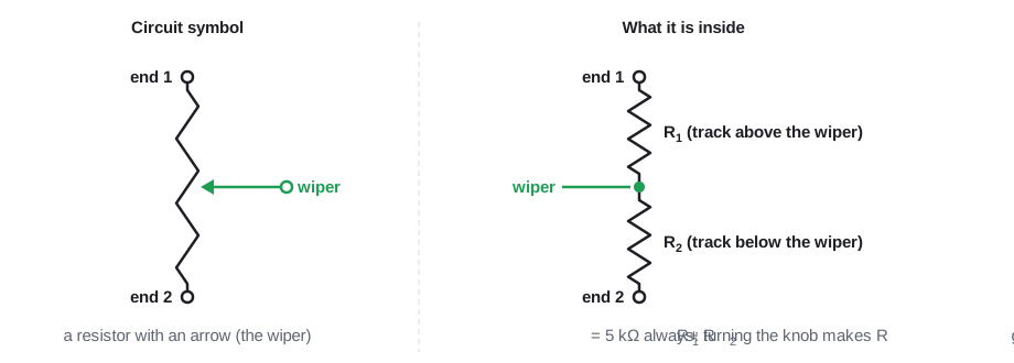
| Knob position | \(R_1\) | \(R_2\) |
|---|---|---|
| Turned fully one way | \(R_{tot} = 5\ \text{k}\Omega\) | 0 |
| Turned fully the other way | 0 | \(R_{tot} = 5\ \text{k}\Omega\) |
| Middle | 2.5 kΩ | 2.5 kΩ |
(Which way counts as “clockwise” depends on which outer pin goes to the supply; swap them and the direction reverses.)
With 5 V across a 5 kΩ pot, it is exactly the divider from Section 3:
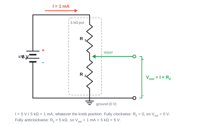
\[I = \frac{5\ \text{V}}{5\ \text{k}\Omega} = 1\ \text{mA}, \qquad V_{out} = I \times R_2\]
- \(R_2 = 0\): \(V_{out} = 1\ \text{mA}\times0 = 0\ \text{V}\)
- \(R_2 = 5\ \text{k}\Omega\): \(V_{out} = 1\ \text{mA}\times5\ \text{k}\Omega = 5\ \text{V}\)
The current stays at 1 mA wherever the knob is, because \(R_1 + R_2\) is always 5 kΩ. Only the split changes. On the bench, a pot across 5 V is a handy stand-in for the RES: turning it lets you test your monitoring code at your desk, as in Read input voltage.
7. On the board: R7 and the SwitchOverADJ trimmer
The RenewableSwitchOver board (its full schematic is in Switching circuitry) uses a fixed resistor and a trimmer for its voltage regulation block:
| Part | Connection |
|---|---|
| J3 (Renew) | RES +ve (the net called Vdrive) and RES −ve (ground, GNDS) |
| R7, 10 kΩ | From Vdrive to the top of the trimmer |
| SwitchOverADJ trimmer | Its track from R7 to GNDS; its wiper is the net AnalogIn |
| AnalogIn | Arduino A0, and test point TP1 (SO_tp) |
So the divider’s “top” resistor is R7 plus the part of the track above the wiper, and the “bottom” resistor is the part of the track below it. With a trimmer of total resistance \(R_T\) and \(R_{low}\) below the wiper:
\[V_{A0} = V_{RES}\,\frac{R_{low}}{10\ \text{k}\Omega + R_T}\]
Turning the trimmer changes \(R_{low}\) from 0 to \(R_T\), so the fraction at A0 can be anything from 0 up to \(R_T/(10\ \text{k}\Omega + R_T)\).
⚠️ Set the trimmer before you trust the reading. With a 10 kΩ trimmer, the largest fraction is \(10/(10+10) = 0.5\): a 16 V RES would put 8 V on A0 with the trimmer turned fully up, well over the 5 V limit. Check the value printed on your trimmer, then:
- Connect the largest voltage the RES can produce (or a bench supply set to it, e.g. 16 V) to J3.
- Measure from TP1 to ground with a multimeter.
- Adjust the trimmer until TP1 reads just under 5 V (4.8 V gives a margin).
Only then connect the Arduino.
Why an adjustable divider?
- Calibration. One board can be matched to sources with different maximum voltages, and resistor tolerances no longer matter: you set the fraction you want, then measure it.
- The switch-over point. The code compares the A0 voltage with a fixed threshold. Turning the trimmer changes the RES voltage at which that threshold is reached, which is why it is called SwitchOverADJ. If the code switches at 2.5 V on A0 and the trimmer gives a fraction \(k\), the RES switches over at \(V_{RES} = 2.5 / k\). With \(k = 0.3\) that is 8.3 V.
Read input voltage shows how the Arduino turns the A0 reading back into the RES voltage, using the fraction you measure here.
Key points
- Arduino analogue inputs must stay within 0–5 V. A higher source voltage must be scaled down, in proportion, before it reaches a pin.
- A divider scales a voltage for measurement; a regulator holds a supply steady for power. The project’s voltage regulation block is a divider.
- \(V_{out} = V_s R_2/(R_1+R_2)\). The ratio sets the voltage; the total resistance sets the current and the power wasted.
- Design from the maximum source voltage: \(R_1 = (V_{max}/5 - 1)\,R_2\), with \(R_2\) around 10 kΩ, rounding \(R_1\) up.
- A potentiometer or trimmer is an adjustable divider. On the board, R7 and the SwitchOverADJ trimmer feed A0: set it at TP1 so the RES maximum gives just under 5 V.
Knowledge check
Test yourself on this chapter. Answers are checked as you go; calculations with New numbers can be tried again with different values.
Why can’t the renewable source (RES) be connected straight to an Arduino analogue input?
The inputs only accept 0–5 V, and the RES may produce 9 V, 12 V or more, which would damage the board
The RES is AC
The Arduino needs at least 20 V to read a voltage
Analogue inputs can only read currents
A 12 V supply drives two 330 Ω resistors in series. Find the current and the voltage across one resistor.
R_T = 2 × 330 = 660 Ω; I = 12 / 660 = 18.2 mA; V₁ = I R₁ = 6 V (equal resistors split the voltage equally).
Two 220 Ω resistors in series are connected across 9 V. What voltage appears across the bottom resistor?
Equal resistors split the voltage equally: 9 × 220/(2 × 220) = 4.5 V
A divider with \(R_1\) = 330 Ω (top) and \(R_2\) = 100 Ω (bottom) is fed from 9 V. Find the current and \(V_{out}\).
I = 9 / (330 + 100) = 20.9 mA; V_out = I R₂ = 2.09 V
A voltage divider has \(R_1\) = 100 Ω and \(R_2\) = 100 Ω across 12 V. What is \(V_{out}\), measured across \(R_2\)?
V_out = V_s R₂/(R₁ + R₂) = 12 × 100 / (100 + 100) = 6 V
The ratio \(R_1/R_2\) fixes \(V_{out}\). What does the absolute size of the resistors set?
The current, and so the power the monitoring circuit wastes
Larger resistors waste less energy, but very large values make the readings noisy; around 10 kΩ for \(R_2\) is a good compromise.
The output voltage
The Arduino’s reference voltage
Nothing
The RES can produce up to 15.86 V, and the Arduino must see 5 V at that maximum. With \(R_2\) = 10 kΩ, what value of \(R_1\) is needed?
Set \(5 = V_{max}\,R_2/(R_1 + R_2)\) and rearrange to \(R_1 = (V_{max}/5 - 1)\,R_2\).
R₁ = (15.86/5 − 1) × R₂ = 2.172 × 10 kΩ = 21.7 kΩ. Round up to the next standard value so V_out stays just under 5 V.
Design a divider giving 6 V at 60 mA from a 12 V battery. Find \(R_1\) and \(R_2\).
Total resistance \(R_T = V_s/I\); \(R_2 = V_{out}/I\); \(R_1 = R_T - R_2\).
R_T = 12 / 0.06 = 200 Ω; R₂ = 6 / 0.06 = 100 Ω; R₁ = R_T − R₂ = 100 Ω
Design a voltage divider from a 12 V battery whose output is 6 V (±0.2) while drawing about 60 mA (±5).
The ratio sets \(V_{out}\) (equal resistors halve the voltage); the total, \(R_T = 12/0.06 = 200\) Ω, sets the current.
A potentiometer’s two outer pins are the ends of a fixed resistance , and the middle pin is the , which splits the track into \(R_1\) and \(R_2\). With 5 V across it, the pot is an adjustable voltage .
A 5 kΩ pot has 5 V across it, and the wiper gives \(R_2\) = 2.5 kΩ. Find the current through the track and the wiper voltage.
I = 5 V / 5 kΩ = 1 mA; V_out = I × R₂ = 1 mA × 2.5 kΩ = 2.5 V
The RES can reach 15.86 V. Choose \(R_1\) and \(R_2\) so the Arduino sees between 4.5 and 5 V at that maximum, while the divider draws under 1 mA (to waste little energy).
\(R_1 = 2.172\,R_2\); for example 22 kΩ and 10 kΩ give 4.96 V at 0.5 mA.
The project’s voltage regulation block is a voltage divider, not a voltage regulator such as a 7805. Why?
A regulator holds its output at a fixed 5 V whatever the RES does, so the Arduino could no longer tell how big the RES voltage is
A regulator can’t work from a renewable source
A divider can power the pump, a regulator can’t
A divider can’t power anything; its output collapses as soon as a load draws current.
Regulators only work on AC
On the board, R7 (10 kΩ) feeds the top of a 10 kΩ SwitchOverADJ trimmer. With the trimmer turned fully up (wiper at the top of its track) and the RES at 16 V, what voltage reaches A0?
With the wiper at the top, the whole trimmer is the bottom resistor of the divider and R7 is the top one.
V_A0 = 16 × 10 / (10 + 10) = 8 V. Anything over 5 V is above the Arduino’s limit, so set the trimmer at TP1 before connecting the Arduino.
Put the steps for setting the SwitchOverADJ trimmer safely in order.
Connect the largest voltage the RES can produce (or a bench supply set to it) to J3
Measure the voltage from TP1 to ground with a multimeter
Adjust the trimmer until TP1 reads just under 5 V
Connect the Arduino