Lecture 8: Phasors and Impedance
Leading and Lagging Waves
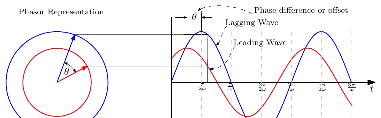
A sine wave can be represented by a phasor: an arrow of length equal to the wave’s amplitude, rotating anticlockwise at angular frequency \(\omega\). The height of the arrow tip traces out the wave. Two waves of the same frequency that are offset by a phase difference \(\theta\) are drawn as two phasors separated by the angle \(\theta\); the wave whose phasor is further ahead (anticlockwise) is the leading wave, the other the lagging wave.
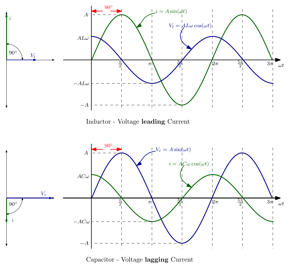
From Lecture 7:
- Inductor: the voltage \(V_l = AL\omega\cos(\omega t)\) leads the current \(i = A\sin(\omega t)\) by 90°.
- Capacitor: the voltage \(V_c = A\sin(\omega t)\) lags the current \(i = AC\omega\cos(\omega t)\) by 90°.
Two questions follow naturally:
- How can we distinguish between currents or voltages leading or lagging by 90°?
- How can we handle a combination of components such as resistors, capacitors and inductors in series or parallel?
The answer to both is the concept of a complex impedance.
Complex Numbers Recap: the j Operator
By now you will have seen complex numbers in the form \(a + ib\), or more commonly in engineering \(a + jb\), where \(i\) or \(j\) is called an imaginary number and given the value \(\sqrt{-1}\). Let’s take a few minutes to conceptualise what the \(j\) operator is, and how it helps with leading and lagging waves and their phase angles.
Arithmetic as movement along a number line
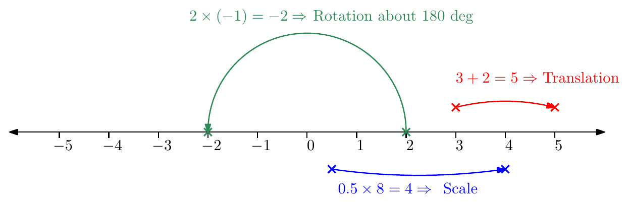
Basic arithmetic operations move us along a number line:
- \(2 \times (-1) = -2\) is a rotation through 180°;
- \(3 + 2 = 5\) is a translation;
- \(0.5 \times 8 = 4\) is a scaling.
Rotating through 90°
Suppose we want to move from 1 to a point directly above the origin, i.e. rotate through 90°. How do we do that arithmetically?
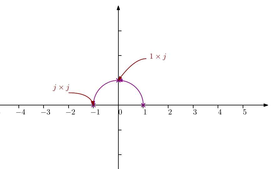
- We have seen that multiplication can cause rotation, so let’s multiply by an as yet unknown number, and call it \(j\).
- \(1 \times j\) takes us to the desired position.
- If we multiply by \(j\) again we should rotate through another 90°, which brings us to the point \(-1\).
- But \(j \times j = j^2\), so
\[ j^2 = -1 \quad \Rightarrow \quad j = \sqrt{-1} \]
The key point for this course:
Multiplying by \(j\) is equivalent to rotating through 90° anticlockwise; multiplying by \(-j\) rotates through 90° clockwise.
So, in answer to the first question: we can show that a current or voltage leads or lags by 90° by multiplying its phasor by \(j\) or \(-j\).
Series RL Circuit: Phasors and Complex Impedance
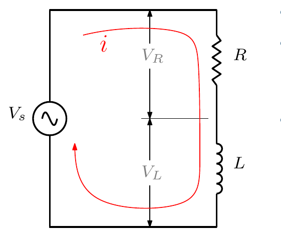
Consider an inductor in series with a resistor. Since the circuit is in series, we are interested in the voltage drops across the components, so we use the current as the reference phasor (the same current flows through every component).
- \(V_s = V_R + V_L\) (as phasors).
- The current \(i\) and the voltage across the resistor \(V_R\) are in phase, so \(V_R = iR\).
- The magnitude of the voltage across the inductor is \(|V_L| = iX_L\), where \(X_L\) is the inductive reactance.
- But \(V_L = iX_L\) alone does not convey that the voltage across an inductor leads the current by 90°. To show this we write
\[ V_L = j\,i\,X_L \]
where \(j\) denotes a rotation through 90°.
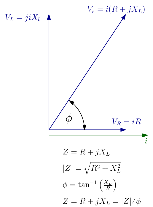
The expression \(V_s = V_R + V_L\) can now be written
\[ V_s = iR + j\,iX_L = i\,(R + jX_L) \]
where \(R + jX_L\) is the complex impedance \(Z\). It is a complex number and can be treated as one in any calculation:
\[ Z = R + jX_L, \qquad |Z| = \sqrt{R^2 + X_L^2}, \qquad \varphi = \tan^{-1}\!\left(\frac{X_L}{R}\right), \qquad Z = |Z|\,\angle\,\varphi \]
The phasor diagram shows the supply voltage relative to the current; trigonometry gives its magnitude and its phase angle \(\varphi\) relative to the current.
Series RC Circuit
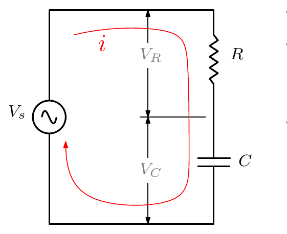
A similar analysis applies to a capacitor in series with a resistor. Again the current is the reference; what matters is the phase difference between the waves, so in a series circuit we align \(V_R\) with the current and draw all other phasors relative to it.
- \(V_s = V_R + V_C\).
- \(V_R = iR\) (in phase with the current).
- The magnitude of the voltage across the capacitor is \(|V_C| = iX_C\), where \(X_C\) is the capacitive reactance.
- To show that this voltage lags the current by 90°, we write
\[ V_C = -j\,i\,X_C \]
where \(-j\) denotes a rotation through 90° clockwise.
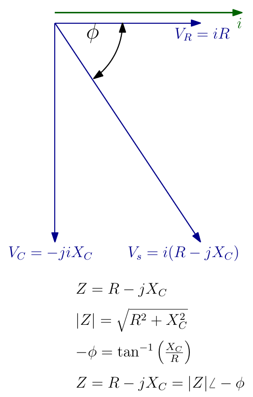
\[ V_s = iR - j\,iX_C = i\,(R - jX_C) \]
\[ Z = R - jX_C, \qquad |Z| = \sqrt{R^2 + X_C^2}, \qquad -\varphi = \tan^{-1}\!\left(\frac{X_C}{R}\right), \qquad Z = |Z|\,\angle -\varphi \]
Combining Impedances
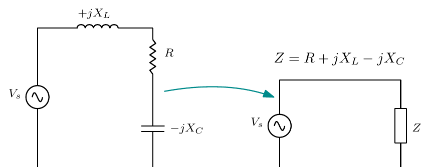
It is common to gather the resistive and reactive components into a single impedance:
\[ Z = R + jX_L - jX_C \]
This lets us use
\[ V = i \times Z \]
to find a voltage or current and its phase difference. Impedances in this form also behave like resistors when simplifying series and parallel combinations:
\[ \text{Series: } Z_{TOT} = Z_1 + Z_2 + \cdots \qquad\qquad \text{Parallel: } \frac{1}{Z_{TOT}} = \frac{1}{Z_1} + \frac{1}{Z_2} + \cdots \]
Worked Examples
A good rule of thumb: draw or visualise the circuit, then sketch an approximate phasor diagram, before calculating.
Example 1: coil (series RL)
A coil having a resistance of 12 Ω and an inductance of 0.1 H is connected across a 230 V, 50 Hz supply. Calculate (a) the reactance and the impedance of the coil, (b) the current, and (c) the phase difference between the current and the applied voltage.
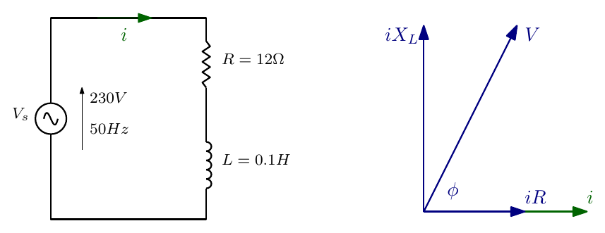
(a)
\[ X_L = 2\pi f L = 2\pi \times 50 \times 0.1 = 31.4\ \Omega \]
\[ Z = \sqrt{R^2 + X_L^2} = \sqrt{12^2 + 31.4^2} = 33.6\ \Omega \]
(b)
\[ i = \frac{V}{Z} = \frac{230}{33.6} = 6.85\ \text{A} \]
(c)
\[ \varphi = \tan^{-1}\!\left(\frac{X_L}{R}\right) = \tan^{-1}\!\left(\frac{31.4}{12}\right) = 69^\circ \]
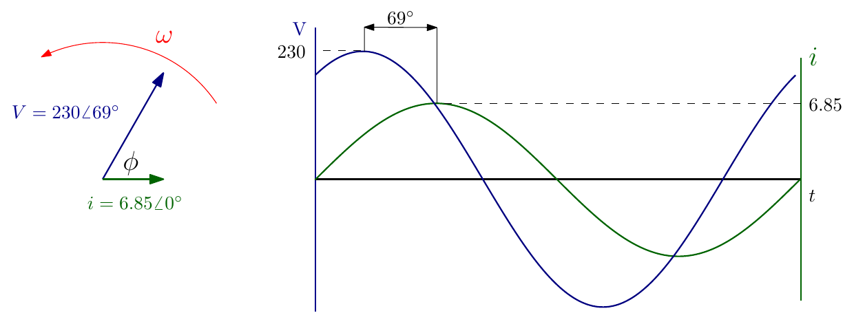
The voltage leads the current by 69°: \(V = 230\angle 69^\circ\) V when \(i = 6.85\angle 0^\circ\) A.
Example 2: capacitor (series RC)
A capacitor of 8.0 µF takes a current of 1.0 A when the alternating voltage applied across it is 230 V. Calculate (a) the frequency of the applied voltage, (b) the resistance to be connected in series with the capacitor to reduce the current in the circuit to 0.5 A at the same frequency, and (c) the phase angle of the resulting circuit.

(a)
\[ X_C = \frac{V}{i} = \frac{230}{1} = 230\ \Omega, \qquad f = \frac{1}{2\pi C X_C} = \frac{1}{2\pi \times 8\times10^{-6} \times 230} = 86.5\ \text{Hz} \]
(b)
\[ Z = \frac{V}{i} = \frac{230}{0.5} = 460\ \Omega, \qquad Z = \sqrt{R^2 + X_C^2} \;\Rightarrow\; 460 = \sqrt{R^2 + 230^2} \;\Rightarrow\; R = 398\ \Omega \]
(c)
\[ \varphi = \tan^{-1}\!\left(\frac{-X_C}{R}\right) = \tan^{-1}\!\left(\frac{-230}{398}\right) = -30^\circ \]
The current leads the voltage by 30°.
Example 3: series RLC
A circuit having a resistance of 12 Ω, an inductance of 0.15 H and a capacitance of 100 µF in series is connected across a 100 V, 50 Hz supply. Calculate (a) the impedance, (b) the current, and (c) the phase difference between the current and the supply voltage.
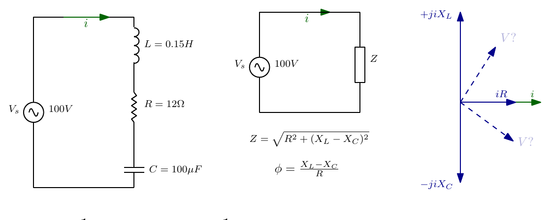
(a)
\[ X_C = \frac{1}{2\pi f C} = \frac{1}{2\pi \times 50 \times 100\times10^{-6}} = 31.85\ \Omega, \qquad X_L = 2\pi f L = 2\pi \times 50 \times 0.15 = 47.1\ \Omega \]
\[ Z = \sqrt{R^2 + (X_L - X_C)^2} = \sqrt{12^2 + (47.1 - 31.85)^2} = 19.4\ \Omega \]
(b)
\[ i = \frac{V}{Z} = \frac{100}{19.4} = 5.15\ \text{A} \]
(c)
\[ \varphi = \tan^{-1}\!\left(\frac{X_L - X_C}{R}\right) = \tan^{-1}\!\left(\frac{47.1 - 31.85}{12}\right) = 51.8^\circ \]
\(X_L > X_C\), so the circuit is inductive overall and the current lags the supply voltage by 51.8°.
Interactive Elements
Each element below runs in the page; use Open full screen for more room.
Rotating phasor and wave
A phasor rotating at \(\omega\) beside the wave it traces, with a second phasor at an adjustable phase difference \(\theta\); the leading and lagging waves are labelled as \(\theta\) changes sign.
The j operator on the complex plane
Click “× j”, “× −j” or “× −1” and watch a point rotate 90° anticlockwise, 90° clockwise or 180°, building the idea that \(j^2 = -1\).
Series RLC phasor builder
Sliders for \(R\), \(L\), \(C\) and frequency; the voltage phasors \(iR\), \(jiX_L\) and \(-jiX_C\) are drawn head to tail to give \(V_s\), with \(|Z|\), \(\varphi\) and the current worked out, and the waveforms underneath. Setting the values of Examples 1–3 reproduces the lecture’s answers, and sweeping the frequency shows the circuit change from capacitive to inductive (passing through resonance, where \(X_L = X_C\)).
Impedance calculator
Build series and parallel combinations of \(Z\) blocks and see the total impedance in rectangular and polar form.
Knowledge Check
Q1. What does multiplying a phasor by \(j\) do? And by \(-j\)?
Answer
Multiplying by \(j\) rotates the phasor 90° anticlockwise (a 90° lead). Multiplying by \(-j\) rotates it 90° clockwise (a 90° lag).
Q2. Using the idea of rotation, explain why \(j^2 = -1\).
Answer
Multiplying by \(j\) rotates through 90°, so multiplying by \(j\) twice rotates through 180°, taking 1 to \(-1\). So \(j \times j = j^2 = -1\).
Q3. In a series circuit, why is the current used as the reference phasor?
Answer
The same current flows through every component in series, so it is common to all of them; each component’s voltage drop can then be drawn relative to it (\(iR\) in phase, \(jiX_L\) leading by 90°, \(-jiX_C\) lagging by 90°).
Q4. Write the complex impedance of a 20 Ω resistor in series with an inductor of reactance 15 Ω, and give its magnitude and angle.
Answer
\(Z = 20 + j15\ \Omega\); \(|Z| = \sqrt{20^2 + 15^2} = 25\ \Omega\); \(\varphi = \tan^{-1}(15/20) = 36.9^\circ\). So \(Z = 25\angle 36.9^\circ\ \Omega\).
Q5. In a series RC circuit, does the supply voltage lead or lag the current?
- Lead, by an angle between 0° and 90°
- Lag, by an angle between 0° and 90°
- Lead, by exactly 90°
- They are in phase
Answer
B. \(Z = R - jX_C\) has a negative angle, so the voltage lags the current (equivalently, the current leads the voltage) by \(\tan^{-1}(X_C/R)\), which is between 0° and 90°.
Q6. A 50 Ω resistor is in series with a capacitor of reactance 50 Ω across a 100 V supply. Find the current and the phase angle.
Answer
\(|Z| = \sqrt{50^2 + 50^2} = 70.7\ \Omega\), so \(i = 100/70.7 = 1.41\) A, and \(\varphi = \tan^{-1}(-50/50) = -45^\circ\) (the current leads the voltage by 45°).
Q7. How are impedances combined in series and in parallel?
Answer
Exactly like resistors, but using complex arithmetic: in series \(Z_{TOT} = Z_1 + Z_2 + \cdots\); in parallel \(1/Z_{TOT} = 1/Z_1 + 1/Z_2 + \cdots\).
Q8. In Example 3, the circuit had \(X_L = 47.1\ \Omega\) and \(X_C = 31.85\ \Omega\). Is the circuit inductive or capacitive overall, and what would happen to the current if \(X_L\) and \(X_C\) were equal?
Answer
Inductive, because \(X_L > X_C\) (the current lags the voltage). If \(X_L = X_C\) the reactances would cancel, \(Z = R = 12\ \Omega\), and the current would be at its maximum, \(100/12 = 8.3\) A, in phase with the voltage (series resonance).
Q9. In Example 1, the coil’s current was 6.85 A. What are the voltage drops across its resistance and its inductance, and do they add up to 230 V?
Answer
\(V_R = iR = 6.85 \times 12 = 82.2\) V and \(V_L = iX_L = 6.85 \times 31.4 = 215\) V. They do not add arithmetically to 230 V, because they are 90° apart: \(\sqrt{82.2^2 + 215^2} = 230\) V. Phasors must be added as vectors.
Q10. A capacitor draws 2 A from a 120 V, 60 Hz supply. What is its capacitance?
Answer
\(X_C = V/i = 120/2 = 60\ \Omega\), so \(C = \dfrac{1}{2\pi f X_C} = \dfrac{1}{2\pi \times 60 \times 60} = 44.2\ \mu\)F.