Non-Vibratory Hopper Feeders and Magazines
Chapter 15 · Part IV: Automated Assembly and Parts Feeding · Sources: Lectures 13 and 14
15.1 Reciprocating tube hopper feeder
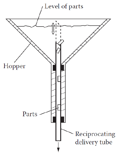
Figure 15.1: A delivery tube reciprocates through a conical hopper, collecting parts.
Design of the hopper angle Φ
Part 1: Φ must be large enough that parts don’t jam.
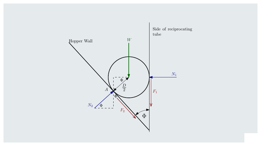
Figure 15.2: Free-body diagram of a cylindrical part of diameter D at the hopper wall and tube.
- Vertical equilibrium: \(F_1 + W + F_2\cos\Phi = N_2\sin\Phi\)
- Horizontal equilibrium: \(N_1 = N_2\cos\Phi + F_2\sin\Phi\)
- Moments about A: \(F_1\dfrac{D}{2}(1 + \cos\Phi) + W\dfrac{D}{2}\cos\Phi = N_1\dfrac{D}{2}\sin\Phi\)
With \(F_2 = \mu N_2\) and, at jamming, \(F_1 = \mu N_1\), rearranging gives \(\mu = \dfrac{1 - \cos\Phi}{\sin\Phi}\). So to avoid jamming:
\[\mu < \frac{1 - \cos\Phi}{\sin\Phi}\]
Part 2: Φ must be small enough that parts slide down the hopper wall.
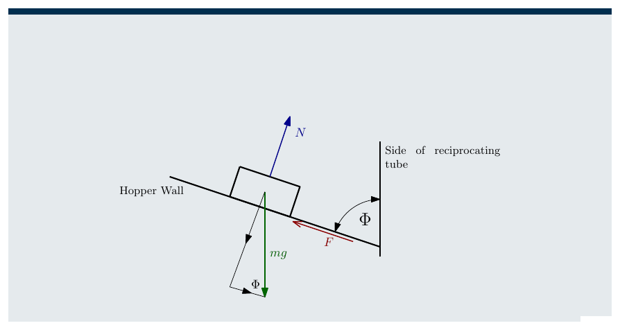
Figure 15.3: A part sliding on the hopper wall.
\[\mu < \cot\Phi\]
Equating the two expressions gives \(\Phi = 60^\circ\):
- For \(\Phi < 60^\circ\), \(\mu < \dfrac{1 - \cos\Phi}{\sin\Phi}\) is the governing limit.
- For \(\Phi > 60^\circ\), \(\mu < \cot\Phi\) is the governing limit.
E.g. for \(\Phi = 45^\circ\), jamming is a problem when \(\mu > 0.41\).
Design notes
- Ideally the hopper should be half full.
- The delivery tube should rise above the maximum fill level.
- The tube’s internal profile should only accept correctly oriented parts.
- The delivery tube’s linear velocity should be below 0.6 m/s.
15.2 Centreboard hopper feeder
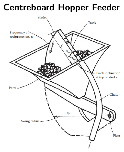
Figure 15.4: A bladed centreboard rises through the parts, collecting some in its track, and tilts them towards the chute.
This analysis finds the track inclination at the top of the stroke that maximises feed rate. The centreboard’s motion has five phases:
- Accelerate uniformly from rest to mid-height.
- Decelerate uniformly from mid-height to stop at maximum height.
- Dwell at maximum height until the parts leave the track.
- Decelerate (accelerate downwards) uniformly from maximum height to mid-height.
- Accelerate uniformly from mid-height to stop at the fully down position.
Phases 1, 2, 4 and 5 all take the same time.
The deceleration in phase 2 is chosen so that the normal reaction between part and track is zero at maximum height, which ensures the part starts to slide down the track.
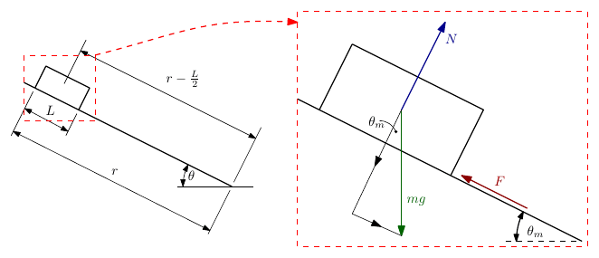
Figure 15.5: The blade pivots about a point at radius r; the part sits at \(r - L/2\).
Cycle time
For zero reaction, track acceleration = acceleration due to gravity:
\[m\ddot{\theta}\left(r - \frac{L}{2}\right) = -mg\cos\theta_m\]
where \(\theta_m\) is the maximum track angle. Since \(L \ll r\), \(\ddot{\theta} = -\dfrac{g\cos\theta_m}{r}\), and during upward motion \(\ddot{\theta} = +\dfrac{g\cos\theta_m}{r}\).
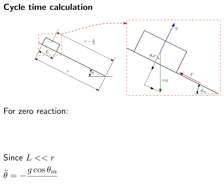
Figure 15.6: Forces on the part during the dwell phase.
Phases 1, 2, 4 and 5. Using \(s = ut + \tfrac{1}{2}ft^2\) with \(s = \theta_m/2\), \(u = 0\) and \(f = g\cos\theta_m/r\):
\[\frac{\theta_m}{2} = \frac{1}{2}\frac{g\cos\theta_m}{r}t^2 \;\Rightarrow\; t = \sqrt{\frac{\theta_m r}{g\cos\theta_m}}\]
Phase 3 (dwell while parts slide). Gravity pushes the part down the track, resisted by friction \(F = \mu N = \mu mg\cos\theta_m\):
\[m\ddot{x} = mg\sin\theta_m - \mu mg\cos\theta_m\]
With \(s = r\) (track length), \(u = 0\):
\[t = \sqrt{\frac{2r}{g(\sin\theta_m - \mu\cos\theta_m)}}\]
Total cycle time:
\[T = 4\sqrt{\frac{\theta_m r}{g\cos\theta_m}} + \sqrt{\frac{2r}{g(\sin\theta_m - \mu\cos\theta_m)}}\]
There is an angle \(\theta_m\) that minimises \(T\). Differentiate with respect to \(\theta_m\), set the result to zero and solve; because the equation is complicated, it is solved numerically.
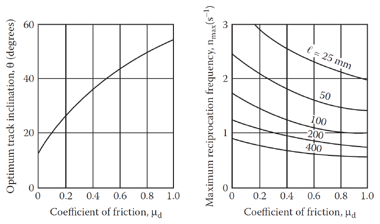
Figure 15.7: Optimum track angle (left) and maximum reciprocation frequency (right) vs coefficient of friction.
Feed rate
Efficiency depends on how many parts are picked up per stroke, which depends on track design and hopper load and is found empirically:
\[F = \frac{\text{number of parts selected}}{\text{total cycle time}}\]
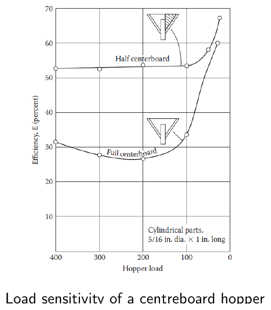
Figure 15.8: Load sensitivity of a centreboard hopper (half and full centreboard).
15.3 Centrifugal hopper feeder
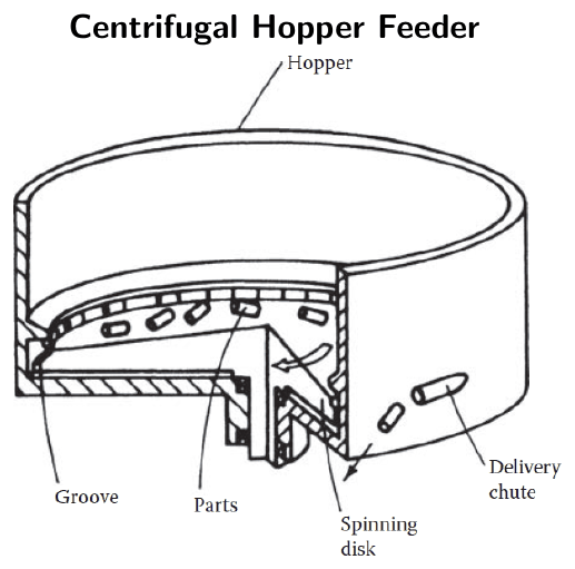
Figure 15.9: A spinning disk throws parts outwards into a groove at the wall, which leads to the delivery chute.
Operation. The rotating base moves the parts around and outwards towards the wall by centrifugal force. At the wall, friction slows the parts, so the base slides beneath them. Eventually the friction force from the base balances the drag from the wall, and the parts move at constant velocity.
\[\text{Radial reaction at wall} = \frac{mv^2}{r}\]
where \(m\) = part mass, \(r\) = hopper radius, \(v\) = part velocity around the inside of the wall.
- Wall friction: \(F_w = \mu_w \dfrac{mv^2}{r}\)
- Base friction: \(F_b = \mu_b mg\)
At equilibrium \(F_w = F_b\):
\[v = \sqrt{\frac{\mu_b g r}{\mu_w}}\]
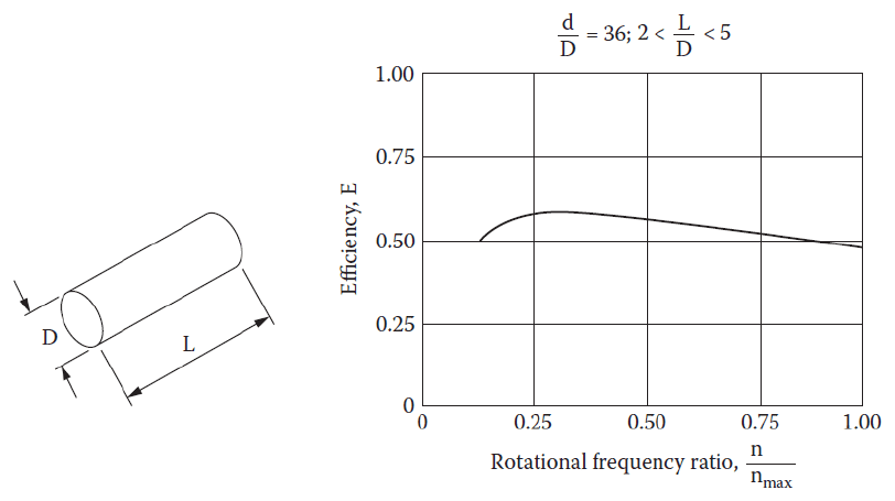
The maximum feed rate is \(v/L\), where \(L\) is the part length. In practice parts don’t line up perfectly at the edge, so an efficiency \(E\) (between 0 and 1) is included:
\[\text{Feed rate} = \frac{E}{L}\sqrt{\frac{\mu_b g r}{\mu_w}}\]
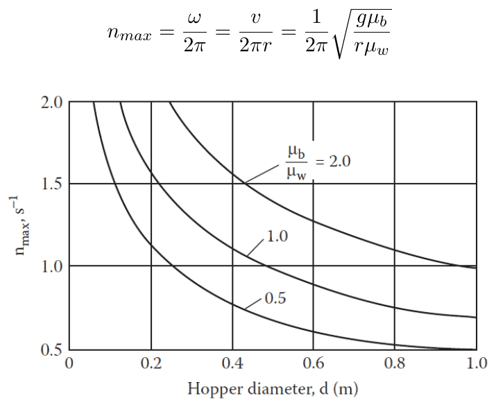
Efficiency is highest at about 25% of the maximum rotational frequency \(n_{max}\), which depends on the ratio of base to wall friction coefficients:
\[n_{max} = \frac{\omega}{2\pi} = \frac{v}{2\pi r} = \frac{1}{2\pi}\sqrt{\frac{g\mu_b}{r\mu_w}}\]
| Efficiency vs rotational frequency ratio | \(n_{max}\) vs hopper diameter |
|---|---|
 |
 |
15.4 Other hopper feeders
| Feeder | Notes | Illustration |
|---|---|---|
| Reciprocating fork | A rotating bowl moves headed parts onto a fork, which rises periodically to transfer them. Analysis is similar to the centreboard hopper. | 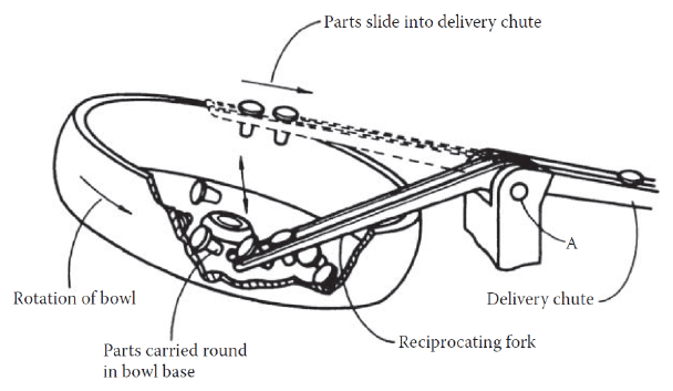 |
| External gate | A rotating inner sleeve with slots passes an external gate. \(\text{Feed rate} = E\,\dfrac{0.802\sqrt{Dg}}{a_s}\), where \(E\) = efficiency, \(D\) = part diameter, \(g\) = gravity, \(a_s\) = slot spacing. | 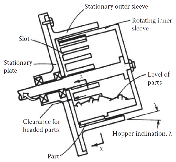 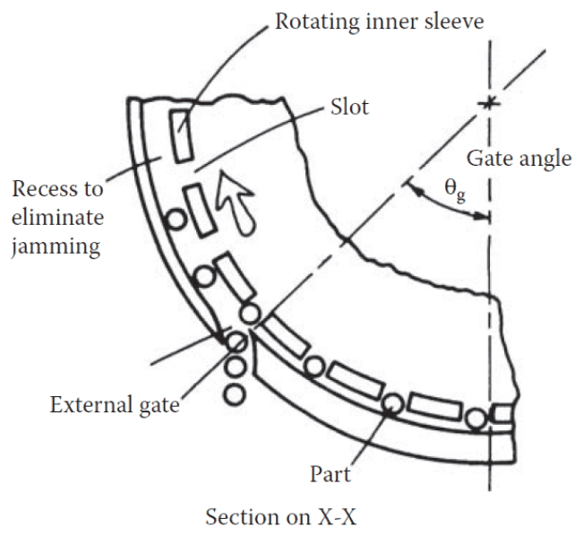 |
| Revolving hook | The hook is the same thickness as the parts; a hood over the chute prevents blockages. | 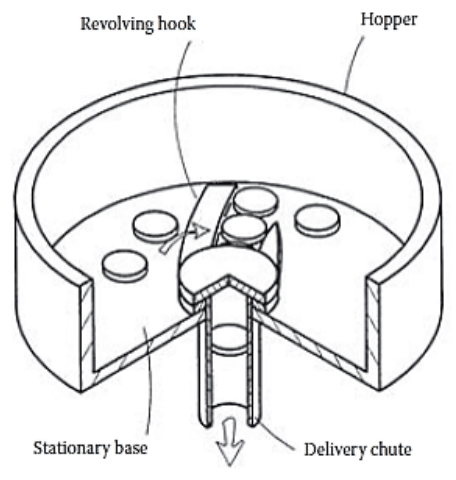 |
| Stationary hook | Parts are deflected to the edge as the base rotates. Gentle, so used for delicate parts. The hook shape is solved numerically to give the parts constant velocity. | 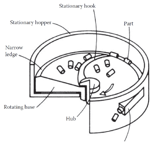 |
| Bladed wheel | The blades push wrongly oriented parts back into the pile; only correctly aligned parts move along the track. Track angle = 45°, blade speed = 0.7 m/s. | 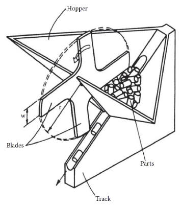 |
| Rotary centreboard | The blade lifts parts and transfers them to a delivery track. Usually driven intermittently by a Geneva or similar mechanism. \(V_{max}\) at blade tip < 0.6 m/s. | 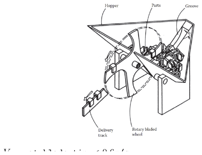 |
| Tumbling barrel | Fins push parts until they drop; some land on a vibratory track, and correctly oriented ones travel out of the feeder. Ideally ¼ full, with a rubber lining to reduce noise and wear. | 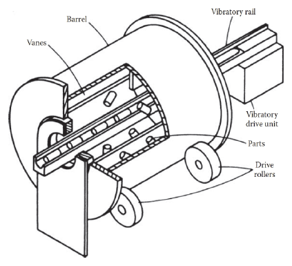 |
| Magnetic disk | For ferromagnetic parts. The magnetic disc diameter should equal the part’s major dimension. | 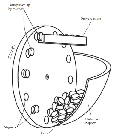 |
| Elevating hopper | A belt with ledges lifts parts out of a stationary hopper to a delivery chute. | 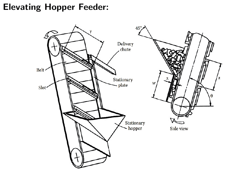 |
| Magnetic elevating hopper | An endless belt with magnets lifts ferromagnetic parts to the feed chute. | 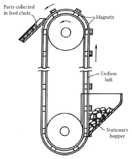 |
15.5 Magazines
Magazines are preloaded stacks of parts.
| Advantages | Disadvantages |
|---|---|
| Accept good parts only, so act as an inspection device | Hold relatively few parts and may need frequent reloading |
| No feed track needed | Should be loaded when the part is made, which isn’t always possible |
| Avoid blockages, and therefore machine downtime | Multiple magazines can increase costs |
| Can be prepared offline with just one feeding device |
Key points
- Reciprocating tube hopper: jamming limit \(\mu < (1-\cos\Phi)/\sin\Phi\), sliding limit \(\mu < \cot\Phi\); they cross at 60°.
- Centreboard: choose phase-2 deceleration so \(N = 0\) at the top; optimise \(\theta_m\) numerically for minimum cycle time.
- Centrifugal: \(v = \sqrt{\mu_b g r/\mu_w}\); best efficiency at about \(0.25\,n_{max}\).
Interactive applets
Each applet runs in the page; use Open full screen for more room, or open all of this chapter’s applets together.
Applet 15.1 · Hopper angle design chart
Plot \((1-\cos\Phi)/\sin\Phi\) and \(\cot\Phi\) against \(\Phi\); enter a friction coefficient and the safe Φ band is shaded. Click a point to see a part jam or slide in an animation.
Teaches: The two design limits and the 60° crossover. · Open full screen ↗
Applet 15.2 · Centreboard cycle-time optimiser
Sliders for \(r\) and \(\mu\); plot \(T(\theta_m)\) with the minimum found numerically and marked, and animate the five-phase blade motion with a phase timeline.
Teaches: The numerical optimisation, and why phase-2 deceleration is chosen for \(N = 0\). · Open full screen ↗
Applet 15.3 · Centrifugal hopper calculator
Enter \(\mu_b\), \(\mu_w\), hopper diameter and part length; outputs \(v\), \(n_{max}\), recommended speed (\(0.25\,n_{max}\)) and feed rate, with a top-down animation of parts circulating.
Teaches: The equilibrium-velocity derivation. · Open full screen ↗
Applet 15.4 · Feeder selector
Answer questions about the part (ferromagnetic? headed? delicate? cylindrical?) and get a ranked shortlist of feeders with reasons.
Teaches: Matching feeder types to part characteristics. · Open full screen ↗