Microcontrollers Part 5 — Voltage dividers for voltage monitoring
Learning outcome
- Construct a voltage divider
1. Why we need it — voltage monitoring
In the design project a renewable energy source (RES) — e.g. a wind turbine — and a backup battery both supply a load (e.g. a pump). The Arduino must monitor the RES voltage to decide which source to use.
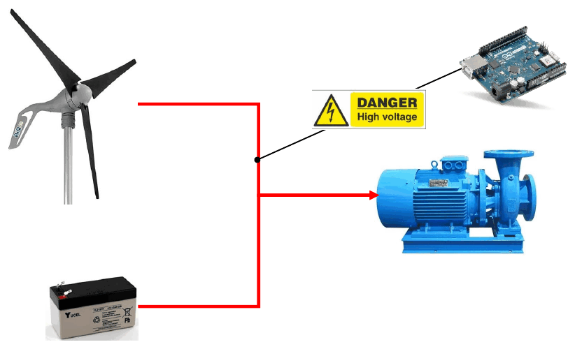
Problem: the Arduino’s analogue inputs only accept 0–5 V. The RES may produce 9 V, 12 V or more — connecting it directly would damage the board (hence the Danger — high voltage sign). A voltage divider scales the voltage down into the safe range.
2. Ohm’s law revision
Two resistors in series: \(R_T = R_1 + R_2\)
Example: \(V_s = 9\ \text{V}\), \(R_1 = R_2 = 220\ \Omega\)
\[R_T = 440\ \Omega, \qquad I = \frac{V}{R} = \frac{9\ \text{V}}{440\ \Omega} \approx 20\ \text{mA}\]
3. Voltage across the bottom resistor
\[V_{out} = IR_2 = (20\times10^{-3}\ \text{A})(220\ \Omega) = 4.4\ \text{V}\]
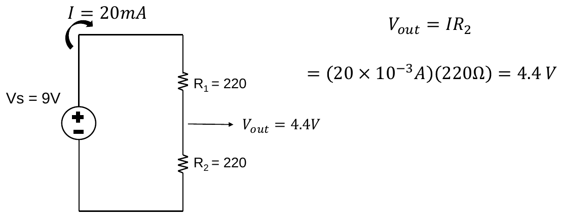
(More precisely \(9 \times \frac{220}{440} = 4.5\ \text{V}\); the slide rounds \(I\) to 20 mA first.)
Unequal resistors: \(R_1 = 330\ \Omega\), \(R_2 = 100\ \Omega\)
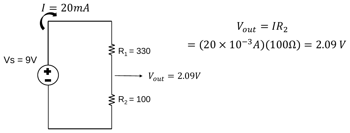
\[I = \frac{9}{430} = 20.9\ \text{mA}, \qquad V_{out} = 20.9\ \text{mA}\times100\ \Omega = 2.09\ \text{V}\]
⚠️ The slide reuses \(I = 20\ \text{mA}\) (from the previous example) in the working, which would give 2.0 V; the correct current for 330 + 100 Ω is 20.9 mA, which gives the stated answer of 2.09 V.
4. The voltage-divider equation
Combine \(I = \dfrac{V_s}{R_1 + R_2}\) and \(V_{out} = IR_2\):
\[\boxed{V_{out} = V_s\left(\frac{R_2}{R_1 + R_2}\right)}\]
Notice that \(V_{out}\) depends only on the ratio of the resistors, not their absolute size. The absolute size sets the current — and therefore how much power the monitoring circuit wastes.
5. Question: how do I work out what resistors I need?
Start from the maximum voltage the source can produce and the voltage you want at the Arduino at that maximum (5 V). The slide’s example has a maximum RES voltage of 15.86 V:
\[5\ \text{V} = 15.86\ \text{V}\left(\frac{R_2}{R_1+R_2}\right)\]
\[5(R_1 + R_2) = 15.86\,R_2\]
\[5R_1 + 5R_2 = 15.86\,R_2\]
\[5R_1 = 10.86\,R_2\]
\[\boxed{R_1 = 2.172\,R_2}\]
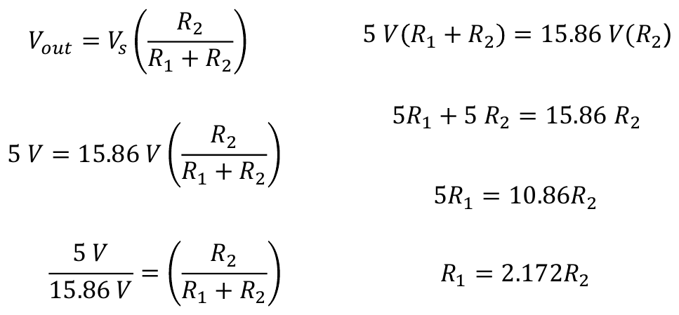
Now choose a convenient \(R_2\) and calculate \(R_1\):
| \(R_2\) | \(R_1 = 2.172R_2\) | Nearest standard \(R_1\) | \(V_{out}\) at 15.86 V | Current |
|---|---|---|---|---|
| 1 kΩ | 2.172 kΩ | 2.2 kΩ | 4.96 V | 5.0 mA |
| 10 kΩ | 21.72 kΩ | 22 kΩ | 4.96 V | 0.50 mA |
| 100 kΩ | 217.2 kΩ | 220 kΩ | 4.96 V | 0.05 mA |
Round \(R_1\) up so that \(V_{out}\) stays just under 5 V. Larger resistances waste less energy (important in a sustainable system), but very large values (≫ 10 kΩ total) make the Arduino’s analogue reading noisier — around 10 kΩ for \(R_2\) is a good compromise.
6. Designing for a set current
If instead you are told the output voltage and the current (from Part 2): 12 V supply, 6 V output, 60 mA:
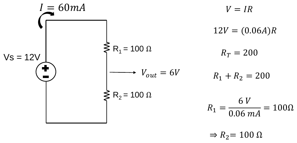
\[R_T = \frac{12\ \text{V}}{0.06\ \text{A}} = 200\ \Omega, \quad R_2 = \frac{6\ \text{V}}{0.06\ \text{A}} = 100\ \Omega, \quad R_1 = 200 - 100 = 100\ \Omega\]
Try it: Voltage divider lab
- Analyse — load any of the slide examples and check \(I\), \(V_{out}\), power and the
analogRead()value. - Design — target \(V_{out}\) and current.
- Scale — enter your source’s maximum voltage and get \(R_1\) as a multiple of \(R_2\), exactly as in §5. · Open full screen ↗
Reading the divider with the Arduino
Connect the mid-point of the divider to an analogue pin and share the ground between the RES circuit and the Arduino:
/*
 * Measure a renewable energy source (RES) voltage through a voltage divider.
 * Divider: R1 = 22 kΩ (top), R2 = 10 kΩ (bottom); mid-point to A0.
 * The RES negative and the Arduino GND must be connected together.
 */

const uint8_t  kResPin     = A0;         // divider mid-point
const float    kR1         = 22000.0;    // top resistor (Ω)
const float    kR2         = 10000.0;    // bottom resistor (Ω)
const float    kRatio      = kR2 / (kR1 + kR2);   // fraction of Vres that reaches the pin: 0.3125
const float    kAdcVref    = 5.0;        // analogRead reference voltage (V)
const float    kAdcMax     = 1023.0;     // largest analogRead value
const uint16_t kSampleMs   = 200;        // time between readings (ms)

void setup() {
  Serial.begin(9600);                    // start the Serial Monitor link
}

void loop() {
  int   reading = analogRead(kResPin);            // 0 to 1023
  float vPin    = reading * (kAdcVref / kAdcMax); // voltage at the A0 pin
  float vRes    = vPin / kRatio;                  // undo the divider: the real RES voltage

  Serial.print("A0: ");                  // prints e.g. "A0: 3.91 V   RES: 12.51 V"
  Serial.print(vPin);
  Serial.print(" V   RES: ");
  Serial.print(vRes);
  Serial.println(" V");
  delay(kSampleMs);
}
Run it in the code runner — move the RES voltage slider and follow the reading back to the source voltage. · Open full screen ↗
Explainer: from a reading back to the source voltage
The calculation runs the divider “backwards” in three steps. With the RES at 12.5 V as an example:
| Step | Line | Example |
|---|---|---|
| 1. The divider scales the RES voltage down | kRatio = kR2 / (kR1 + kR2) |
10 000 ÷ 32 000 = 0.3125, so the pin sees 12.5 × 0.3125 = 3.91 V |
| 2. The ADC turns the pin voltage into a number | analogRead(kResPin) |
3.91 ÷ 5 × 10²³ ≈ 800 |
| 3a. Convert the number back to the pin voltage | reading * (kAdcVref / kAdcMax) |
800 × 5 ÷ 1023 = 3.91 V |
| 3b. Undo the divider | vPin / kRatio |
3.91 ÷ 0.3125 = 12.5 V |
kRatiois calculated from the two resistor values, so if you change a resistor you only changekR1orkR2.- Variables declared inside
loop()(reading,vPin,vRes) are created fresh on every pass. They are only needed there, so keeping them inside makes it clear where they are used. - Accuracy: the result is only as good as the resistor tolerance (±5 % resistors give up to ±5 % error) and the 5 V reference. For better accuracy, measure the actual resistor values and use those in
kR1andkR2.
Key points
- Arduino analogue inputs must stay within 0–5 V — always scale a higher source voltage with a divider.
- \(V_{out} = V_s R_2/(R_1+R_2)\); design from the maximum source voltage.
- The ratio sets the voltage; the total resistance sets the current and wasted power.
- Divide the measured pin voltage by \(R_2/(R_1+R_2)\) to recover the true source voltage.