Microcontrollers Part 6 — Potentiometers and analogRead
Learning outcome
- Use a potentiometer to vary voltages going to the Arduino
1. What is a potentiometer?
A potentiometer (“pot”) can be thought of as a variable resistor. In the project it stands in for a renewable source whose voltage rises and falls — letting you test your monitoring code at your desk.
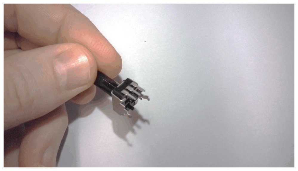
2. How it works
A pot has a resistive track of fixed total resistance \(R_{tot}\) (here 5 kΩ) between its two outer pins, and a wiper (middle pin) that slides along it. The wiper splits the track into two resistors:
\[R_{tot} = R_1 + R_2\]
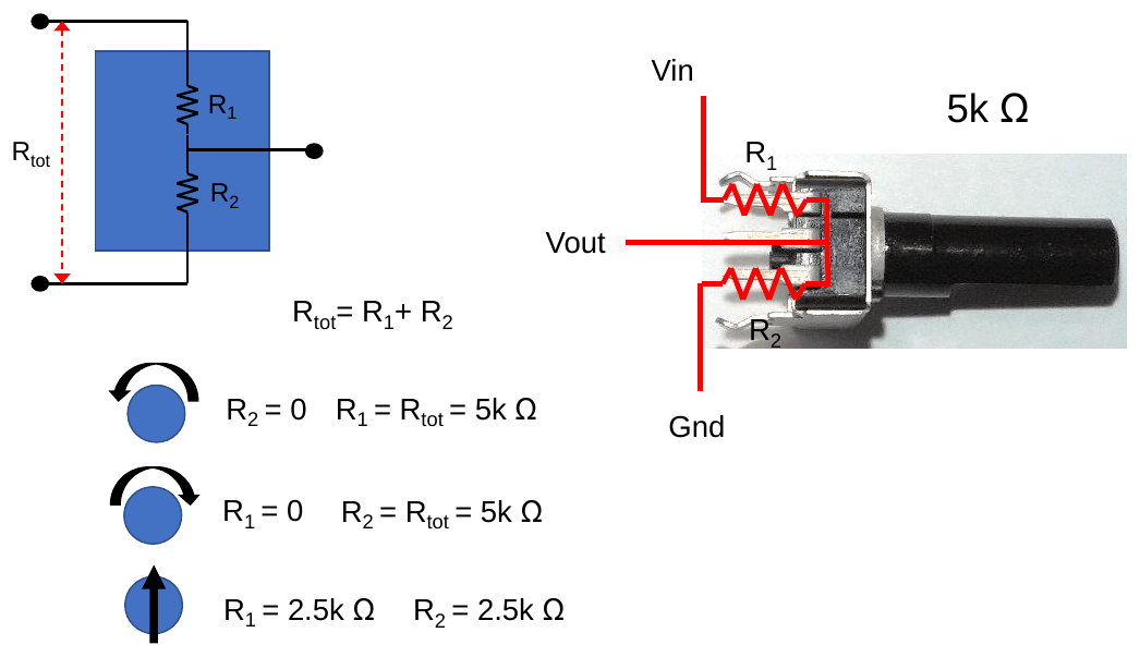
| Knob position | \(R_1\) | \(R_2\) |
|---|---|---|
| Turned fully one way | \(R_{tot} = 5\ \text{k}\Omega\) | 0 |
| Turned fully the other way | 0 | \(R_{tot} = 5\ \text{k}\Omega\) |
| Middle | 2.5 kΩ | 2.5 kΩ |
With the outer pins on 5 V and GND, the wiper output is a voltage divider you can adjust by hand.
3. Calculating the output voltage
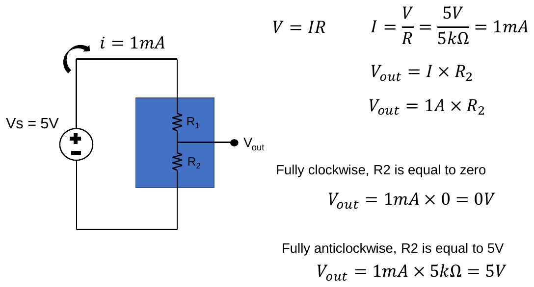
The current through the whole track is constant:
\[I = \frac{V}{R} = \frac{5\ \text{V}}{5\ \text{k}\Omega} = 1\ \text{mA}\]
The wiper voltage is the voltage across \(R_2\):
\[V_{out} = I \times R_2\]
- Fully clockwise, \(R_2 = 0\): \(V_{out} = 1\ \text{mA}\times 0 = 0\ \text{V}\)
- Fully anticlockwise, \(R_2 = 5\ \text{k}\Omega\): \(V_{out} = 1\ \text{mA}\times 5\ \text{k}\Omega = 5\ \text{V}\)
(Which direction is “clockwise = 0 V” depends on which outer pin you connect to 5 V — swap them to reverse it.)
⚠️ Slide typos: “\(V_{out} = 1\ \text{A}\times R_2\)” should read 1 mA; “R2 is equal to 5 V” should read 5 kΩ.
4. Reading a voltage: analogRead
The analogue pins (A0–A5) contain a 10-bit analogue-to-digital converter: \(2^{10} = 1024\) levels.
| Voltage on pin | analogRead() returns |
|---|---|
| 0 V | 0 |
| 2.5 V | ≈ 512 |
| 5 V | 1023 |
Convert back to volts with:
\[V = \frac{5}{1023}\times\text{reading}\]
Write the constants as 5.0 and 1023.0 (with decimal points) so C++ does floating-point division: 5/1023 in whole numbers is 0!
5. Exercise 2d — read the pot voltage
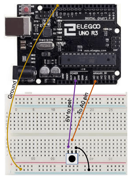
Design and build a circuit and write a programme that reads in voltage values that vary when using a potentiometer.
Circuit: pot outer pins → 5 V and GND; wiper → A1.
/*
 * Exercise 2d: Read the potentiometer voltage and print it.
 * Hardware: pot outer pins to 5 V and GND, wiper to A1.
 */

const uint8_t  kPotPin   = A1;       // pot wiper
const float    kAdcVref  = 5.0;      // analogRead reference voltage (V)
const float    kAdcMax   = 1023.0;   // largest analogRead value
const uint16_t kSampleMs = 500;      // time between readings (ms)

// Read an analogue pin and return the voltage on it (0 to 5 V).
float readVolts(uint8_t pin) {
  int reading = analogRead(pin);              // 0 to 1023
  return reading * (kAdcVref / kAdcMax);      // scale to volts
}

void setup() {
  Serial.begin(9600);                // start the Serial Monitor link
  // Analogue pins are inputs by default, so no pinMode() is needed.
}

void loop() {
  float vOut = readVolts(kPotPin);   // wiper voltage
  Serial.println(vOut);              // one value per line, ideal for the Serial Plotter
  delay(kSampleMs);
}
Run it: Exercise 2d in the code runner — turn the simulated pot and follow readVolts(). · Open full screen ↗
Open Tools › Serial Monitor (or Serial Plotter for a live graph) and turn the knob.
Explainer
readVolts(pin)wraps the two steps (read, then convert) in a function that hands back the answer withreturn. Its return type isfloatbecause a voltage has decimals. The same function is reused in Exercises 2d2 and 2e.- No
pinMode(): analogue pins start up as inputs. The slide’spinMode(Vout, INPUT)passed the voltage variable instead of the pin, so it configured the wrong thing. float vOutinsideloop()is a fresh variable on each pass; it only exists whileloop()runs.
6. Exercise 2d1 — dimmer switch
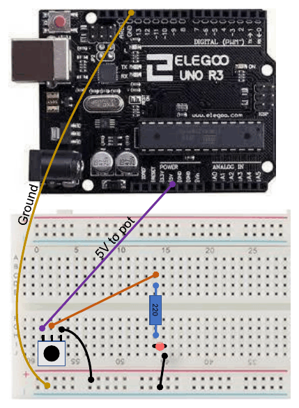
Design a circuit that allows you to increase and decrease the brightness of a red LED using a potentiometer.
Circuit: as 2d, plus a red LED with a 220 Ω resistor on a PWM pin.
/*
 * Exercise 2d1: Use the potentiometer as a dimmer for a red LED.
 * Hardware: pot wiper to A1; red LED + 220 Ω resistor on D10 (a PWM pin).
 */

const uint8_t kPotPin = A1;     // pot wiper
const uint8_t kRedPin = 10;     // must be a PWM (~) pin

void setup() {
  Serial.begin(9600);
  pinMode(kRedPin, OUTPUT);     // LED pin is an output
}

void loop() {
  int reading    = analogRead(kPotPin);                // 0 to 1023
  int brightness = map(reading, 0, 1023, 0, 255);      // rescale to 0 to 255
  analogWrite(kRedPin, brightness);                    // set the LED brightness
  Serial.println(brightness);
}
Run it: Exercise 2d1 in the code runner — turn the simulated pot and watch map() set the LED brightness. · Open full screen ↗
Explainer: matching the two ranges
analogReadgives 0–1023 (10 bits), butanalogWritetakes 0–255 (8 bits).map(value, fromLow, fromHigh, toLow, toHigh)rescales a number from one range to another: 0 → 0, 1023 → 255, and everything in between in proportion (e.g. 512 → 127).- Dividing by 4 (
reading / 4) gives almost the same result, because 1024 ÷ 4 = 256.mapmakes the intent clearer and works for any pair of ranges. - There is no
delay()here, so the brightness follows the knob immediately.
7. Exercise 2d2 — switch at 2.5 V
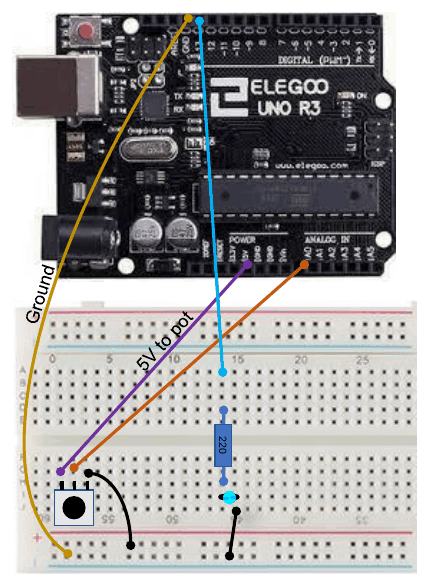
Design a circuit and programme that turns on a blue LED above 2.5 V and turns it off below 2.5 V — using the potentiometer.
/*
 * Exercise 2d2: Blue LED on above 2.5 V, off at or below 2.5 V.
 * Hardware: pot wiper to A1; blue LED + 220 Ω resistor on D13.
 */

const uint8_t  kPotPin    = A1;       // pot wiper
const uint8_t  kBluePin   = 13;       // blue LED
const float    kThreshold = 2.5;      // switching voltage (V)
const float    kAdcVref   = 5.0;
const float    kAdcMax    = 1023.0;
const uint16_t kSampleMs  = 500;

float readVolts(uint8_t pin) {
  return analogRead(pin) * (kAdcVref / kAdcMax);   // reading -> volts
}

void setup() {
  Serial.begin(9600);
  pinMode(kBluePin, OUTPUT);
}

void loop() {
  float vOut = readVolts(kPotPin);
  Serial.println(vOut);

  if (vOut > kThreshold) {
    digitalWrite(kBluePin, HIGH);     // above 2.5 V: LED on
  } else {
    digitalWrite(kBluePin, LOW);      // 2.5 V or below: LED off
  }

  delay(kSampleMs);
}
Run it: Exercise 2d2 in the code runner — move the pot either side of 2.5 V and see which branch runs. · Open full screen ↗
Explainer: making a decision with if ... else
if (vOut > kThreshold)tests a condition. If it is true, the first block runs; otherwise theelseblock runs. Exactly one of the two always runs, so the LED is never left in the wrong state.kThresholdis a named constant, so changing the switching point means editing one number.- The slide’s solution had the test the wrong way round (
Vout < 2.5→ HIGH), which lights the LED below 2.5 V. The version above matches the exercise.
This threshold logic is exactly what the final project uses to decide when the renewable source voltage is too low.
8. Exercise 2e — three voltage bands
Turn on a red LED between 0 and 2 V, a green LED between > 2 and 3.5 V, and a blue LED between > 3.5 and 5 V.
/*
 * Exercise 2e: Show which voltage band the pot is in.
 *   0 to 2 V     -> red LED
 *   >2 to 3.5 V  -> green LED
 *   >3.5 to 5 V  -> blue LED
 * Hardware: pot wiper to A1; LEDs + 220 Ω resistors on D11, D12, D13.
 */

const uint8_t  kPotPin   = A1;
const uint8_t  kRedPin   = 11;
const uint8_t  kGreenPin = 12;
const uint8_t  kBluePin  = 13;
const float    kLowMax   = 2.0;       // top of the red band (V)
const float    kMidMax   = 3.5;       // top of the green band (V)
const float    kAdcVref  = 5.0;
const float    kAdcMax   = 1023.0;
const uint16_t kSampleMs = 500;

float readVolts(uint8_t pin) {
  return analogRead(pin) * (kAdcVref / kAdcMax);
}

// Turn each LED on (true) or off (false) in one call.
void setLeds(bool red, bool green, bool blue) {
  digitalWrite(kRedPin,   red   ? HIGH : LOW);
  digitalWrite(kGreenPin, green ? HIGH : LOW);
  digitalWrite(kBluePin,  blue  ? HIGH : LOW);
}

void setup() {
  Serial.begin(9600);
  pinMode(kRedPin, OUTPUT);
  pinMode(kGreenPin, OUTPUT);
  pinMode(kBluePin, OUTPUT);
}

void loop() {
  float vOut = readVolts(kPotPin);
  Serial.println(vOut);

  if (vOut <= kLowMax) {
    setLeds(true, false, false);      // 0 to 2 V: red only
  } else if (vOut <= kMidMax) {
    setLeds(false, true, false);      // above 2 V, up to 3.5 V: green only
  } else {
    setLeds(false, false, true);      // above 3.5 V: blue only
  }

  delay(kSampleMs);
}
Run it: Exercise 2e in the code runner — move the pot through the three bands and watch the else if chain. · Open full screen ↗
Explainer: choosing one of three bands
if ... else if ... elsechecks the conditions in order and runs only the first one that is true:- Is it 2 V or less? → red.
- If not, is it 3.5 V or less? → green. (We already know it is above 2 V, so there is no need to test that again.)
- Otherwise → blue.
- This chain replaces the slide’s three separate
ifstatements with&&. It is shorter, and because only one branch runs, exactly one LED is ever lit. setLeds(true, false, false)sets all three LEDs in one line, which makes each branch easy to read.red ? HIGH : LOWis the ternary operator: “ifredis true useHIGH, otherwise useLOW”. It is a one-lineif ... else.
| Operator | Meaning |
|---|---|
<, <=, >, >= |
less than, less or equal, greater, greater or equal |
== |
equal to (two =!) |
&& |
AND — both conditions true |
\|\| |
OR — either condition true |
Try it: Potentiometer applet — the “2e: three bands” tab lights the right LED as you turn the knob. · Open full screen ↗
Key points
- A pot is an adjustable voltage divider: \(V_{out} = I\times R_2\), from 0 to 5 V.
analogRead→ 0–1023; convert with(5./1023.) * reading.analogRead(0–1023) ÷ 4 →analogWrite(0–255).if / elsewith comparison and&&operators turns a voltage into decisions.