Lecture 16: Single-Phase Motors
Recap: the Speed–Torque Curve
The lecture opens by revisiting the induction motor’s speed–torque curve and its four key points: starting (locked-rotor), pull-up, pull-out (breakdown) and rated torque. This is covered in full in Lecture 15: The Speed–Torque Curve and is not repeated here.
Torque Curve with a Load
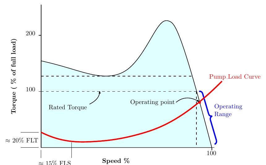
The figure shows a typical load curve for a fan or pump on the motor’s speed–torque curve.
- At low speeds a “stiction” effect is seen (about 20% of full-load torque up to about 15% of full-load speed): the torque needed to overcome friction and the inertia of the material being pumped.
- Above that, the torque required is proportional to the speed squared:
\[ T_{load} \propto N^2 \]
- Since power is torque times speed, the power required to drive the pump is proportional to the speed cubed:
\[ P_{load} = T\,\omega \propto N^3 \]
- The motor settles at the operating point, where the motor’s torque equals the load’s.
The operating point is self-correcting:
- If extra load is applied to the pump, the speed falls and the motor’s torque rises (moving up the steep part of its curve). The increase in torque restores the pump to its operating point.
- If the load on the pump is reduced, the speed rises and the motor’s torque falls, again returning it to the operating point.
NEMA Design Classes
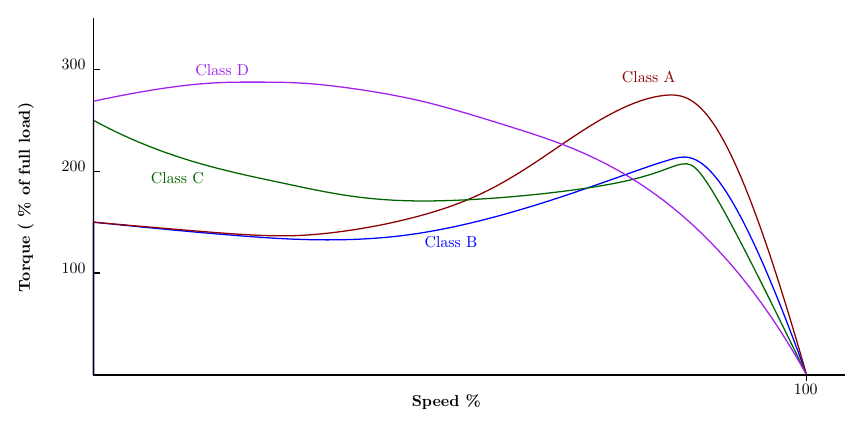
The two main motor standards are those of the National Electrical Manufacturers Association (NEMA) and the International Electrotechnical Commission (IEC). NEMA standards apply mostly in North America and areas of US influence such as the Middle East; IEC standards are covered towards the end of the course.
Speed–torque curves are more readily available for NEMA motor types. Some equivalences exist between NEMA and IEC, but the key point is that motors can be specified by the shape of their speed–torque curve.
| Class A | Class B | Class C | Class D | |
|---|---|---|---|---|
| Basic characteristic | Normal locked-rotor torque | Normal locked-rotor torque | High locked-rotor torque | Very high locked-rotor torque |
| Locked-rotor torque (% of full load) | 70–275% | 70–275% | 70–275%* | 275% |
| Pull-up torque (% of full load) | 65–190% | 65–190% | 65–190%* | not given |
| Breakdown torque (% of full load) | 175–300% | 175–200% | 190–225% | 275–300% |
| Slip | 0.5–5% | 0.5–5% | 1–5% | 5–8% |
| Applications | Fans, blowers, centrifugal pumps and compressors, motor-generator sets, where starting torque requirements are relatively low | As class A | Conveyors, crushers, stirring motors, agitators, reciprocating pumps and compressors, where starting under load is required | High peak loads, with or without flywheels: punch presses, shears, elevators, extractors, winches, hoists, oil-well pumping, wire drawing |
| Efficiency | High or medium | High or medium | Medium | Low |
* The slide gives the same locked-rotor and pull-up ranges for class C as for classes A and B, and labels it “normal” locked-rotor torque. NEMA class C motors are high-starting-torque designs (typically around 200–250% locked-rotor torque, as the curve shows), so treat those two cells with care. The class D pull-up torque is left blank on the slide.
Single-Phase Induction Motors
The vast majority of industrial motors are three-phase, but there is a significant need for single-phase induction motors in small enterprises and domestic settings. The main issue with a single-phase induction motor is starting. Once the rotor is turning, the alternating field keeps it turning.
In a three-phase motor, the rotating stator field is set up by the phase delay between the three phases. That is not possible with a single phase.
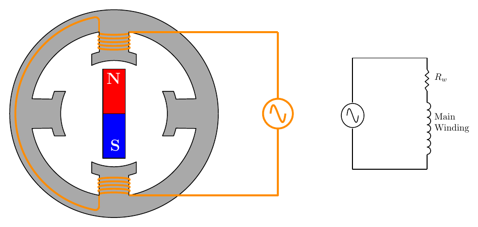
- An alternating current through the single main winding induces an alternating magnetic field in the rotor, represented by the bar magnet.
- But there is no net torque on the rotor: the magnetic attraction and repulsion act through the centre of the rotor.
- If the rotor does start to spin, its direction cannot be guaranteed. Consider the effect of this on a domestic vacuum cleaner!
There are three main methods of starting a single-phase induction motor:
- Capacitor start (and capacitor run)
- Split phase
- A shaded pole
Capacitor Start and Capacitor Run
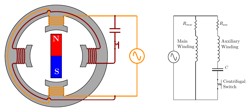
- Starting torque is developed by adding an auxiliary winding, physically at 90° to the main winding (dark red in the figure).
- The auxiliary winding is connected to the same single-phase supply as the main winding.
- A capacitor in series with the auxiliary winding shifts the phase of its current by up to 90° relative to the main winding.
- This delay, together with the 90° spacing of the windings, sets up a rotating magnetic field, which produces torque on the rotor and makes it turn.
Two versions:
- Capacitor start: the auxiliary winding is connected through a centrifugal switch. When the rotor reaches a certain speed the switch opens, and all the current flows through the main winding.
- Capacitor run: there is no centrifugal switch; the capacitor and auxiliary winding stay in circuit while the motor runs.
Typical applications with small starting torques include fans, where the load torque is proportional to the speed squared, so there is hardly any load torque (other than friction) at starting.
Split-Phase Starting

- In the capacitor motor, the capacitor creates the phase difference between the main and auxiliary windings.
- The split-phase motor has no capacitor. Instead, the auxiliary winding is made with relatively thin wire, so that its resistance dominates.
- The main winding is mainly inductive (its current lags well behind the voltage); the auxiliary winding is mainly resistive (its current is closer to being in phase with the voltage).
- This sets up a phase delay between the two winding currents, giving a rotating magnetic field that produces torque on the rotor.
Shaded-Pole Motor
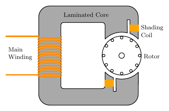
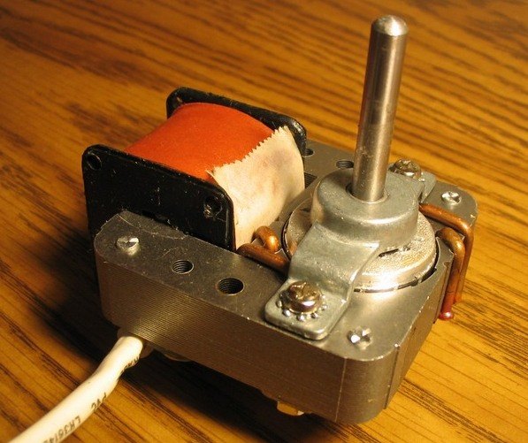
- The shaded-pole motor is one of the most common motors, because it is probably the cheapest to make.
- It has only one main winding: a simple coil wound round the laminated stator core.
- As with the other single-phase motors, a second field is needed to produce a rotating field and develop torque in the rotor.
- A heavy ring of copper or aluminium, the shading ring, is fitted around part of each pole shoe.
- The alternating flux through the ring induces an e.m.f. in it, which drives a current round the ring. Because the ring’s resistance is very low, this current is relatively large, and it creates a second field.
- The direction and size of this field depend on the rate of change of the flux, \(\dfrac{d\Phi}{dt}\) (Lenz’s law): the ring opposes changes in the flux through the shaded part of the pole.
- As the main flux rises and falls, the flux is pushed out of, or concentrated into, the shaded part of the pole. This sets up a field that moves across the pole, which rotates the rotor.
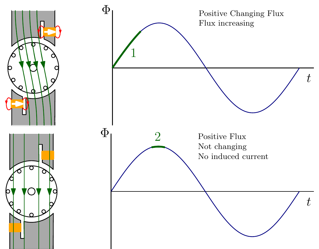
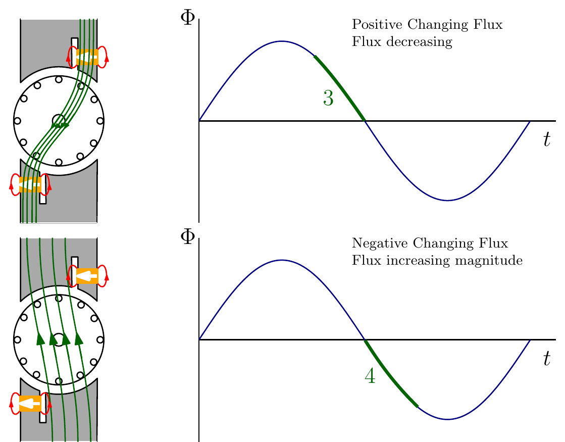
| Step | Main flux \(\Phi\) | Ring current | Where the flux is concentrated |
|---|---|---|---|
| 1 | Positive, increasing | Opposes the increase | Unshaded part of the pole |
| 2 | Positive, not changing (peak) | None | Spread evenly across the pole |
| 3 | Positive, decreasing | Opposes the decrease | Shaded part of the pole |
| 4 | Negative, increasing in magnitude | Opposes the increase | Unshaded part of the pole |
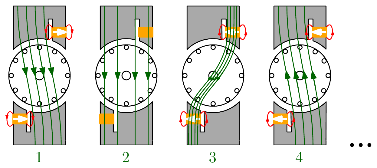
The varying flux establishes a field that sweeps from the unshaded to the shaded part of each pole: in effect a rotating stator field, so the rotor always turns towards the shaded part of the pole.
Interactive Elements
Each element below runs in the page; use Open full screen for more room.
Motor and load curves
Pick a load type (pump or fan with \(T \propto N^2\), constant torque such as a conveyor, or a hard-to-start load) and a NEMA class; the two curves are drawn and the operating point found where they cross. Run-up is animated: the motor accelerates while its torque exceeds the load’s. A load step shows the speed dropping slightly and recovering, and a load too heavy for the pull-up or breakdown torque shows the motor stalling.
Pump affinity laws
A speed slider for a pump showing torque \(\propto N^2\) and power \(\propto N^3\), demonstrating why reducing a pump’s speed by 20% roughly halves its power.
Single-phase rotating field
Main and auxiliary winding currents with an adjustable phase shift (0° to 90°), and the resulting stator field vector. At 0° the field only pulses back and forth; at 90° it rotates at constant strength; in between it traces an ellipse. Switch between capacitor start, capacitor run and split phase to see the phase shift each typically gives.
Shaded-pole animation
The main flux waveform with a moving marker, and the flux in the pole shifting from the unshaded to the shaded side through the four steps, the shading-ring current shown as \(\propto -d\Phi/dt\).
Knowledge Check
Q1. For a centrifugal pump, how do the torque and the power required depend on speed?
Answer
Torque \(\propto N^2\) and power \(\propto N^3\) (above the low-speed “stiction” region).
Q2. A pump’s speed is reduced to 80% of its original value. Roughly what fraction of the original power does it now need?
Answer
\(0.8^3 = 0.51\), so about half the power.
Q3. Explain how an induction motor driving a pump returns to its operating point when extra load is applied.
Answer
The extra load slows the motor. On the steep part of its speed–torque curve, a small drop in speed (an increase in slip) produces a large increase in motor torque, which accelerates the load back towards the operating point where motor torque and load torque are equal.
Q4. Which NEMA class would you choose for a punch press with a flywheel, and why?
Answer
Class D: very high locked-rotor and breakdown torque and high slip (5–8%), so the speed drops under peak loads, letting the flywheel release its stored energy. Its efficiency is lower.
Q5. Which NEMA class suits a conveyor that must start fully loaded?
Answer
Class C, designed for applications where starting under load is required (conveyors, crushers, reciprocating compressors).
Q6. Why does a single-phase induction motor with only a main winding not start on its own?
Answer
A single winding produces a field that only pulses back and forth along one axis; it does not rotate. The forces on the rotor act through its centre, giving no net torque at standstill. (If the rotor is spun by hand, it will keep running in either direction.)
Q7. What is the difference between a capacitor-start and a capacitor-run motor?
Answer
In a capacitor-start motor the auxiliary winding and capacitor are disconnected by a centrifugal switch once the motor is up to speed. In a capacitor-run motor there is no centrifugal switch, so they stay in circuit while running.
Q8. How does a split-phase motor create a phase difference between its windings without a capacitor?
Answer
Its auxiliary winding is made of thinner wire, so it is mainly resistive, while the main winding is mainly inductive. The two currents therefore have different phase angles, which with the 90° spacing of the windings gives a (roughly) rotating field.
Q9. Why is the shaded-pole motor so common, and what is the role of the shading ring?
Answer
It is very cheap and simple: one winding and no switches or capacitors. The shading ring is a short-circuited copper or aluminium loop around part of each pole. The current induced in it opposes changes in the flux through the shaded part (Lenz’s law), delaying the flux there, so the field moves across the pole from the unshaded to the shaded side, producing a (weak) rotating field.
Q10. In which direction does a shaded-pole motor rotate?
Answer
From the unshaded part of each pole towards the shaded part, the direction in which the field sweeps across the pole. The direction is fixed by the construction and cannot simply be reversed electrically.