Lecture 11: Three-Phase Power
Three-Phase Power
- Everything we have seen so far on the AC side has been single phase: a single voltage and current.
- This is perfectly acceptable for domestic and some industrial applications.
- As power demand grew, alternative ways were sought to improve power transfer. This led to multiple (poly) phase transmission, and the industry standard has become three phases.
- The delay between the phases gives constant power transfer over each cycle.
- It also makes it possible to produce a rotating magnetic field in an electric motor, among other advantages.
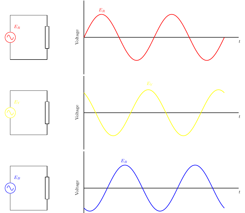
A three-phase supply consists of three voltages of equal amplitude and frequency, \(E_R\), \(E_Y\) and \(E_B\) (red, yellow and blue phases), each 120° apart.
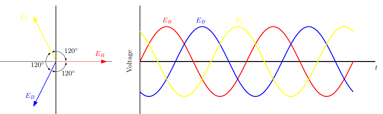
What does it mean to connect the phases together?
Star and Delta Connections
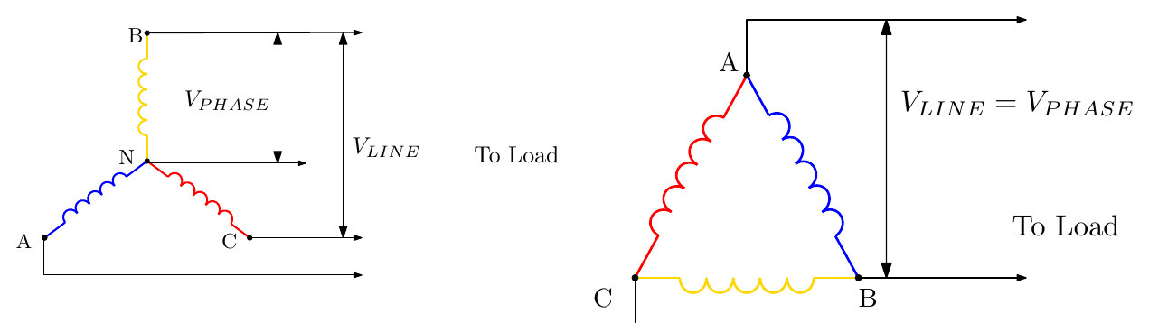
There are two basic methods of connecting the phases together:
- Star (wye): one end of each phase is joined at a common neutral point \(N\); the other ends feed the lines.
- Delta: the phases are connected end to end in a triangle; the three junctions feed the lines, so \(V_{LINE} = V_{PHASE}\).
Definitions
- Line voltage: the voltage measured between any two line conductors in a balanced three-phase system.
- Phase voltage: the voltage measured across any one component in a balanced three-phase source or load.
- Line current: the current through any one line conductor.
- Phase current: the current through any one component.
Star Distributed System
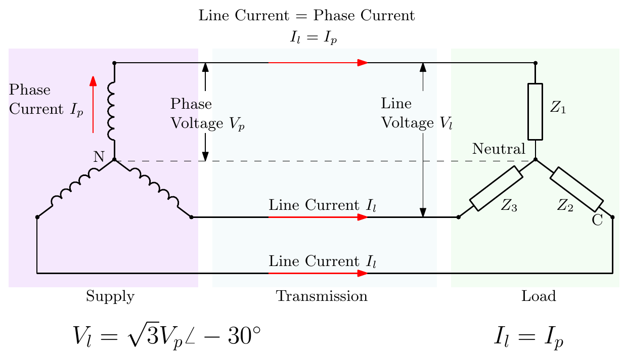
- When loads are unbalanced, a neutral is connected between the supply’s neutral point and the load’s.
- No current flows in the neutral wire when the loads are balanced.
- The three line voltages are 120° apart, and the line voltages lead the phase voltages by 30°.
\[ I_l = I_p, \qquad V_l = \sqrt{3}\,V_p\angle 30^\circ \]
(The slide writes \(\angle -30^\circ\), describing the phase voltage relative to the line voltage; equivalently, the line voltage leads by 30°.)
Delta Distributed System
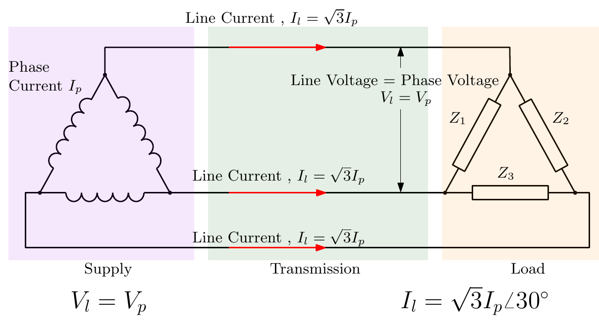
- In a delta-connected supply, the three junction points are connected to the line wires leading to the load.
- When the generator phases are connected correctly, no appreciable current circulates within the delta loop when there is no external load.
- If one phase is reversed, a short-circuit current flows round the windings, causing damage.
- The three line currents are 120° apart, and the line currents lag the phase currents by 30°.
\[ V_l = V_p, \qquad I_l = \sqrt{3}\,I_p\angle -30^\circ \]
(The slide’s diagram writes \(\angle 30^\circ\); the bullet above, that the line currents lag the phase currents, gives \(\angle -30^\circ\).)
Power in a Three-Phase System
Star and delta connections each contain three separately connected loads (\(Z_1, Z_2, Z_3\)). The total real power is the sum of the powers in the three phases:
\[ P = P_1 + P_2 + P_3 = V_1I_1\cos\varphi_1 + V_2I_2\cos\varphi_2 + V_3I_3\cos\varphi_3 \]
For a balanced load, the total power is three times the power in each phase:
\[ P = 3\,V_pI_p\cos\varphi \]
Using the line–phase relationships above, it can be shown that for both star and delta connections
\[ P = \sqrt{3}\,V_lI_l\cos\varphi \]
where \(\varphi\) is the phase angle of each load impedance. Similarly, \(Q = \sqrt{3}\,V_lI_l\sin\varphi\) and \(S = \sqrt{3}\,V_lI_l\).
Examples
1. In a balanced three-phase system the line voltage is 110 V and the line current is 12 A. If the power factor is 0.8, determine the active power.
Solution (worked for these notes):
\[ P = \sqrt{3} \times 110 \times 12 \times 0.8 = 1829\ \text{W} \approx 1.83\ \text{kW} \]
2. In a balanced three-phase system the line voltage is 230 V and the line current is 8 A. If the power factor is 0.75, determine the active power, the reactive power and the apparent power.
Solution (worked for these notes):
\[ S = \sqrt{3} \times 230 \times 8 = 3187\ \text{VA}, \qquad P = 0.75\,S = 2390\ \text{W}, \qquad Q = S\sqrt{1 - 0.75^2} = 2108\ \text{VAR} \]
Advantages of Three-Phase Systems
- A three-phase system can transmit more power than a single-phase system for the same conductor size.
- Three-phase devices and appliances are more efficient than single-phase machines.
- A three-phase system delivers constant power, while a single-phase system delivers pulsating power; three-phase machines therefore run more smoothly and with less vibration.
- A three-phase machine of the same rating occupies less space than a single-phase machine.
- Three-phase motors are self-starting; single-phase motors cannot start on their own.
- Three-phase motors have a better power factor than single-phase motors.
- A single-phase supply can be taken from a three-phase supply to run single-phase machines, but a three-phase machine cannot run from a single-phase supply*.
* Inverters and variable frequency drives (VFDs) can run three-phase equipment from a single-phase input by generating a pseudo three-phase supply.
Star–Delta Conversions
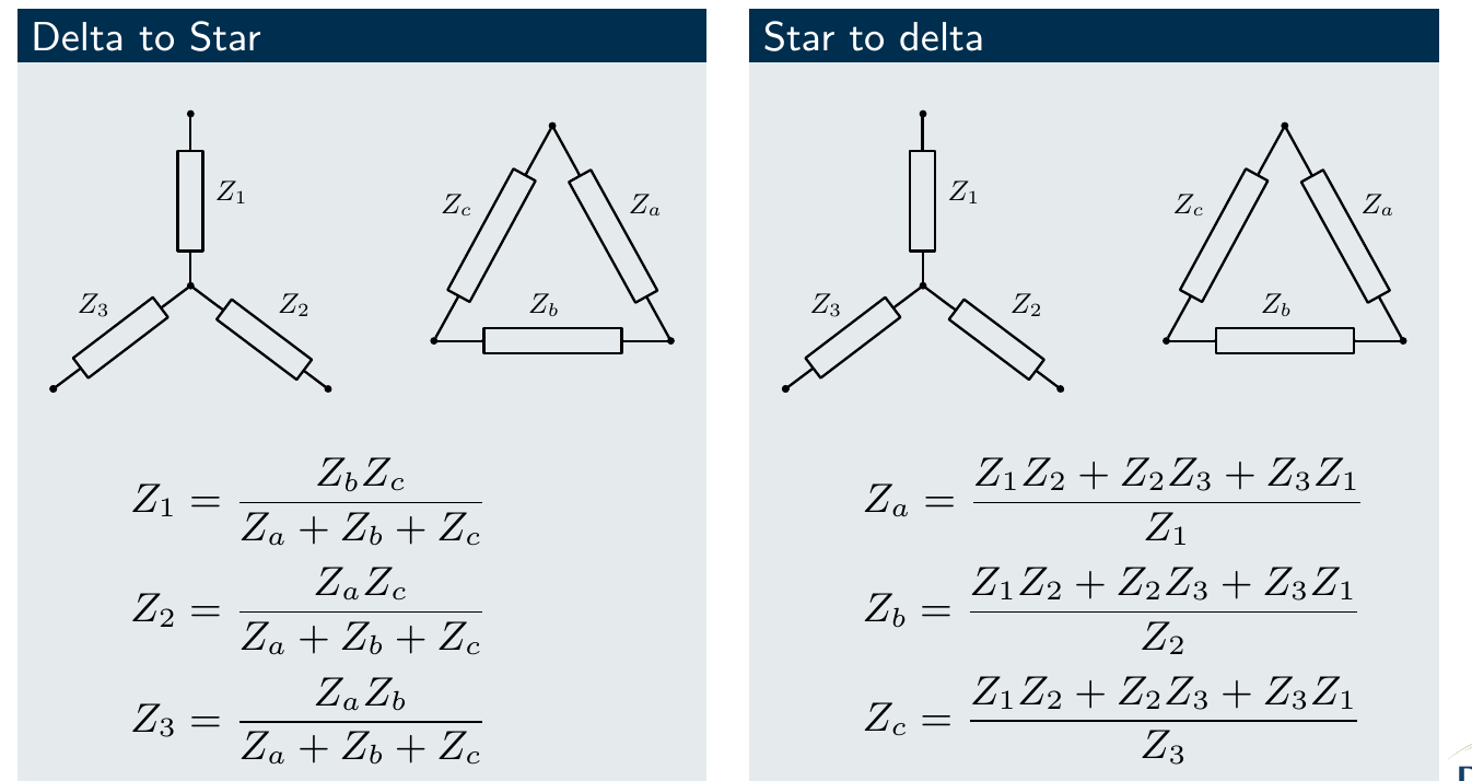
When solving three-phase problems it is often useful to convert between star and delta equivalent circuits; problems are usually easier to solve in star form.
Delta to star
\[ Z_1 = \frac{Z_bZ_c}{Z_a + Z_b + Z_c}, \qquad Z_2 = \frac{Z_aZ_c}{Z_a + Z_b + Z_c}, \qquad Z_3 = \frac{Z_aZ_b}{Z_a + Z_b + Z_c} \]
Star to delta
\[ Z_a = \frac{Z_1Z_2 + Z_2Z_3 + Z_3Z_1}{Z_1}, \qquad Z_b = \frac{Z_1Z_2 + Z_2Z_3 + Z_3Z_1}{Z_2}, \qquad Z_c = \frac{Z_1Z_2 + Z_2Z_3 + Z_3Z_1}{Z_3} \]
For a balanced load (all three impedances equal) these reduce to
\[ Z_Y = \frac{Z_\Delta}{3}, \qquad Z_\Delta = 3\,Z_Y \]
Star–Star Example
The three-phase, star-connected distribution system shown supplies power to a balanced load through transmission lines with impedance \(Z_{line} = R_{line} + jX_{line} = 0.4 + j0.2\ \Omega\). The voltage sources are \(V_{rn} = 115\angle 0^\circ\), \(V_{yn} = 115\angle -120^\circ\) and \(V_{bn} = 115\angle 120^\circ\) V. The load impedances are \(Z_Y = 12 + j6\ \Omega\).
- Calculate the magnitude and phase of the current supplied to each phase of the load. (b) Calculate the total true power (kW) and reactive power (kVAR) in the load. (c) Calculate the total true power (W) and reactive power (VAR) in the transmission lines. (d) Calculate the magnitude of the line-to-line voltage delivered to the load. (e) Draw a phasor diagram of the line-to-neutral voltages and the phase currents delivered to the load.
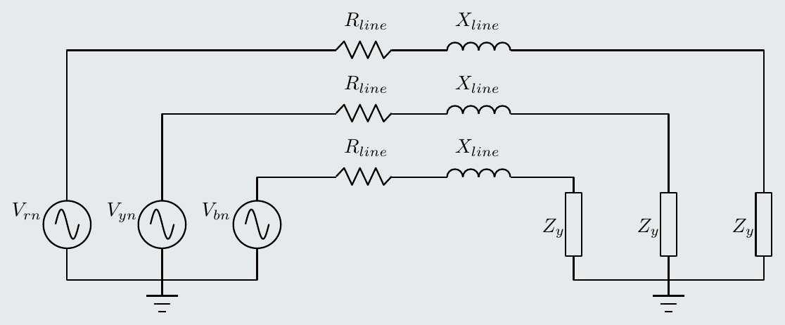
Solution (worked for these notes). The system is balanced, so we can analyse one phase and shift the results by ±120° for the others.
(a) Each phase sees the line and load impedances in series:
\[ Z = Z_{line} + Z_Y = (0.4 + 12) + j(0.2 + 6) = 12.4 + j6.2\ \Omega = 13.86\angle 26.57^\circ\ \Omega \]
\[ I_r = \frac{115\angle 0^\circ}{13.86\angle 26.57^\circ} = 8.30\angle -26.57^\circ\ \text{A}, \qquad I_y = 8.30\angle -146.57^\circ\ \text{A}, \qquad I_b = 8.30\angle 93.43^\circ\ \text{A} \]
(b) In the load:
\[ P = 3I^2R = 3 \times 8.30^2 \times 12 = 2.48\ \text{kW}, \qquad Q = 3I^2X = 3 \times 8.30^2 \times 6 = 1.24\ \text{kVAR} \]
(c) In the lines:
\[ P = 3 \times 8.30^2 \times 0.4 = 82.6\ \text{W}, \qquad Q = 3 \times 8.30^2 \times 0.2 = 41.3\ \text{VAR} \]
(d) The line-to-neutral voltage at the load is
\[ V_{p} = I\,|Z_Y| = 8.30 \times \sqrt{12^2 + 6^2} = 8.30 \times 13.42 = 111.3\ \text{V} \]
so the line-to-line voltage at the load is
\[ V_l = \sqrt{3} \times 111.3 = 192.8\ \text{V} \]
(compared with \(\sqrt{3} \times 115 = 199.2\) V at the source: about 6.4 V is lost in the lines).
(e) The three load voltages are 111.3 V at 0°, −120° and 120° (the line and load impedances have the same angle, so the load voltages stay in phase with the sources), and the three currents are 8.30 A, each lagging its voltage by 26.57°.
Interactive Elements
Each element below runs in the page; use Open full screen for more room.
Three-phase generator
Three phasors rotating 120° apart beside their waveforms, with the instantaneous total power shown to be constant for a balanced load (against the pulsating single-phase power).
Star and delta calculator
Choose star or delta, set the phase voltage and a balanced load impedance, and see line and phase voltages and currents with the √3 and 30° relationships drawn on a phasor diagram, plus \(P\), \(Q\) and \(S\).
Unbalanced star load
Make one phase’s load different and watch a current appear in the neutral, which is zero only when the loads are balanced.
Star–delta converter
Enter \(Z_a, Z_b, Z_c\) or \(Z_1, Z_2, Z_3\) and convert either way, with the balanced case showing \(Z_Y = Z_\Delta/3\).
Knowledge Check
Q1. What is the phase difference between the voltages of a three-phase supply?
Answer
120°.
Q2. In a star-connected system, how are the line and phase voltages related? And the line and phase currents?
Answer
\(V_l = \sqrt{3}\,V_p\) (the line voltages lead the phase voltages by 30°), and \(I_l = I_p\).
Q3. In a delta-connected system, how are the line and phase voltages related? And the line and phase currents?
Answer
\(V_l = V_p\), and \(I_l = \sqrt{3}\,I_p\) (the line currents lag the phase currents by 30°).
Q4. The UK and Irish low-voltage supply is 230 V phase (line to neutral). What is the line-to-line voltage?
Answer
\(V_l = \sqrt{3} \times 230 \approx 400\) V.
Q5. When does current flow in the neutral of a star-connected system?
Answer
Only when the loads are unbalanced. With a balanced load the three phase currents sum to zero, so no current flows in the neutral.
Q6. Write the expression for the total real power of a balanced three-phase load in terms of line quantities. Does it apply to star, delta or both?
Answer
\(P = \sqrt{3}\,V_lI_l\cos\varphi\), which applies to both star and delta connections.
Q7. A balanced delta load has \(Z_\Delta = 30 + j15\ \Omega\) per phase. What is the equivalent star impedance?
Answer
\(Z_Y = Z_\Delta/3 = 10 + j5\ \Omega\) per phase.
Q8. Give three advantages of three-phase systems over single phase.
Answer
Any three of: more power for the same conductor size; higher efficiency; constant (non-pulsating) power, giving smoother, vibration-free machines; smaller machines for the same rating; self-starting motors; better power factor; single-phase supplies can be taken from a three-phase system.
Q9. Why must the phases of a delta-connected generator be connected the right way round?
Answer
Correctly connected, the three phase voltages sum to zero round the delta, so no current circulates with no load. If one phase is reversed, the voltages no longer cancel and a large short-circuit current circulates in the windings, damaging them.
Q10. A balanced three-phase motor takes 20 A from a 400 V (line) supply at a power factor of 0.85. What is its input power?
Answer
\(P = \sqrt{3} \times 400 \times 20 \times 0.85 \approx 11.8\) kW.