Lecture 5: DC Motor Control
Speed Control of Field Wound Electric Motors
The speed of a DC field wound motor can be given by:
\[ N = K\,\frac{V_s - i_a R_a}{\Phi} \]
Where:
- \(V_s\) = Supply voltage
- \(i_a\) = Armature current
- \(R_a\) = Coil resistance
- \(\Phi\) = Magnetic flux per pole
- \(K\) = Motor constants such as number of conductors, number of pole pairs on the motor, how the windings are made on the motor. We will cover these in more detail later but these are constant for any given motor.
Methods of speed control
\[ N = K\,\frac{V_s - i_a R_a}{\Phi} \]
From the equation it can be determined the speed can be controlled by varying:
| Quantity varied | Symbol | Method |
|---|---|---|
| Flux/pole | \(\Phi\) | Flux control |
| Armature resistance | \(i_a\) | Rheostatic control |
| Applied voltage | \(V_s\) | Voltage control |
Speed Control of Shunt Motors
Variation of Flux or Flux Control Method
It can be seen from the speed equation in the previous section that
\[ N \propto \frac{1}{\Phi} \]
By decreasing the flux the speed can be increased and vice versa.
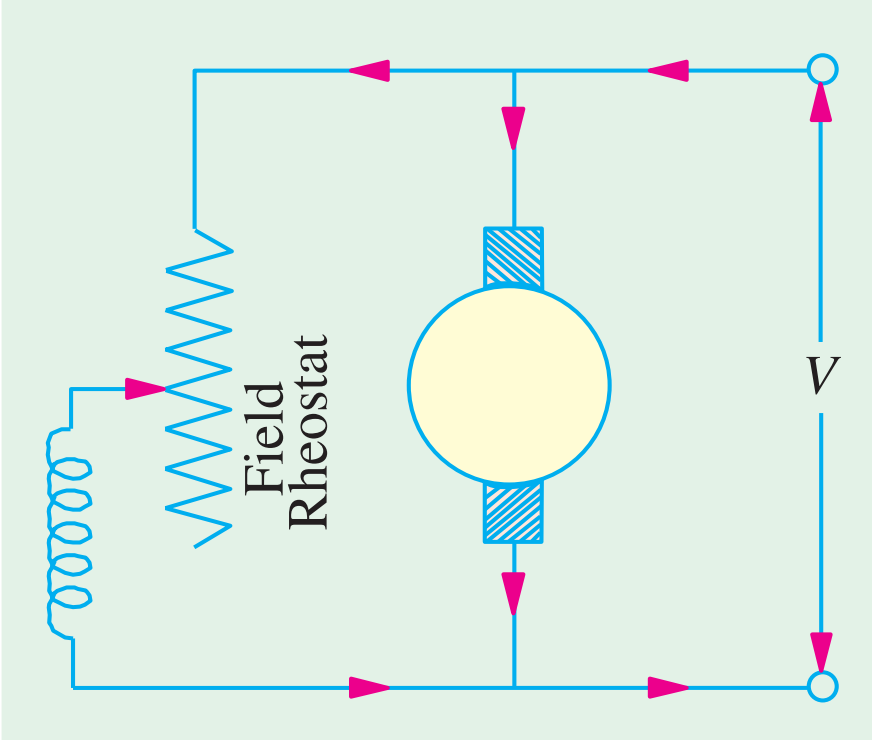
- The flux of the motor can be changed by changing \(I_{sh}\) with help of a shunt field rheostat.
- Since \(I_{sh}\) is relatively small, the shunt field rheostat has to carry only a small current, which means the \(I_{sh}^2 R\) loss is small.
Armature or Rheostatic Control Method
As the supply voltage is normally constant, the voltage across the armature is varied by inserting a variable rheostat in series with the armature circuit.
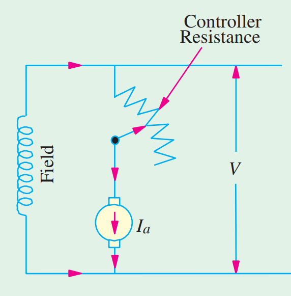
- As controller resistance is increased, voltage across the armature is decreased, thereby decreasing the armature speed.
- For a constant load torque, speed is approximately proportional to the voltage across the armature.
Speed Control of Series Motors
Flux Control Method
Variations in the flux of a series motor can be brought about in any one of the following ways:
Field Diverters
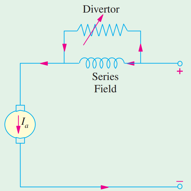
- The series windings are shunted by a variable resistance known as a field diverter.
- Hence the flux can be decreased and, consequently, the speed of the motor increased.
Armature Diverter
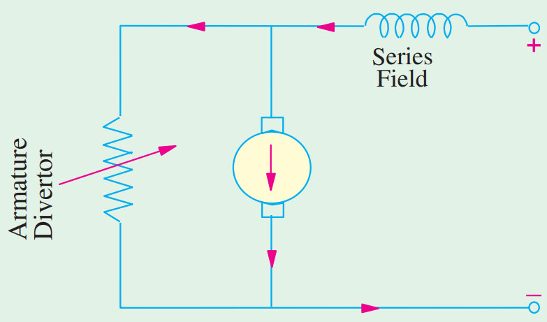
- A diverter across the armature can be used for giving speeds lower than the normal speed.
- For a given constant load torque, if \(I_a\) is reduced due to the armature diverter, \(\Phi\) must increase, since
\[ T_m \propto \Phi I_a \]
- This results in an increase in current taken from the supply (which increases the flux) and a fall in speed, since \(N \propto 1/\Phi\).
Tapped Field Control
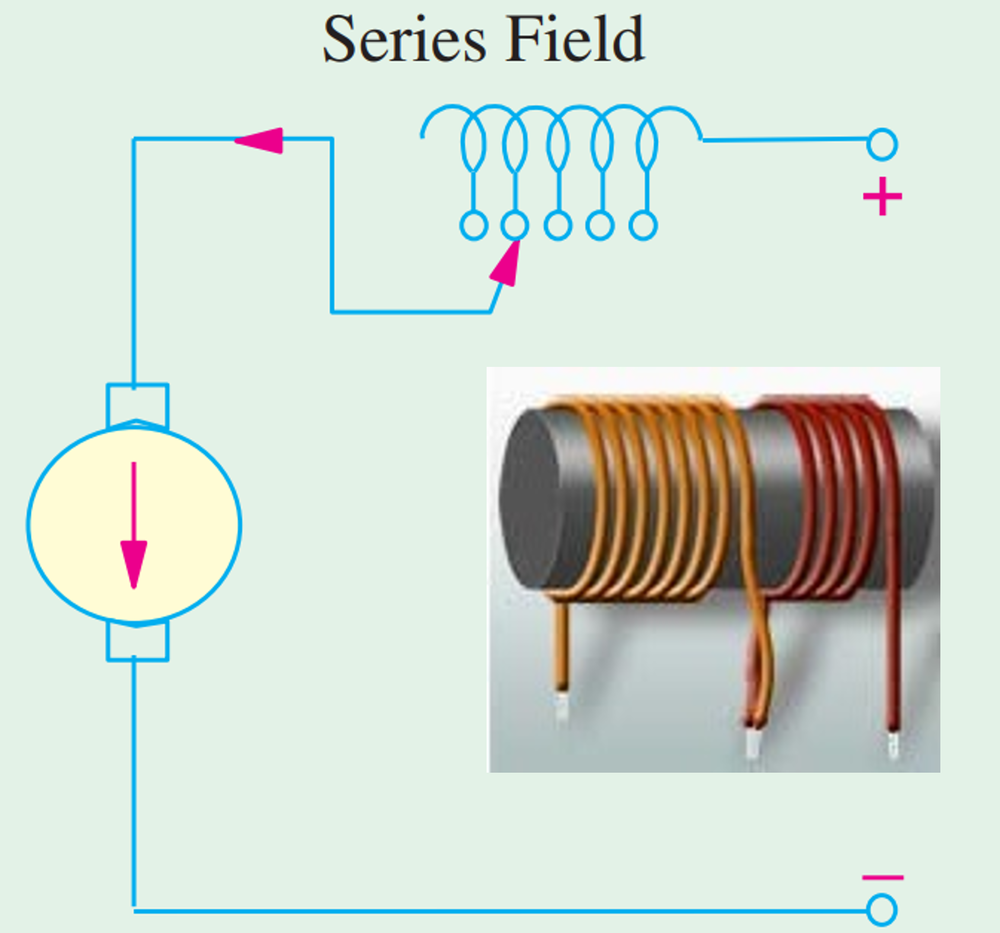
- The number of series field turns in the circuit can be changed.
- With full field, the motor runs at its minimum speed, which can be raised in steps by cutting out some of the series turns.
Variable Resistance in Series with Motor
By increasing the resistance in series with the armature, the voltage applied across the armature terminals can be decreased.
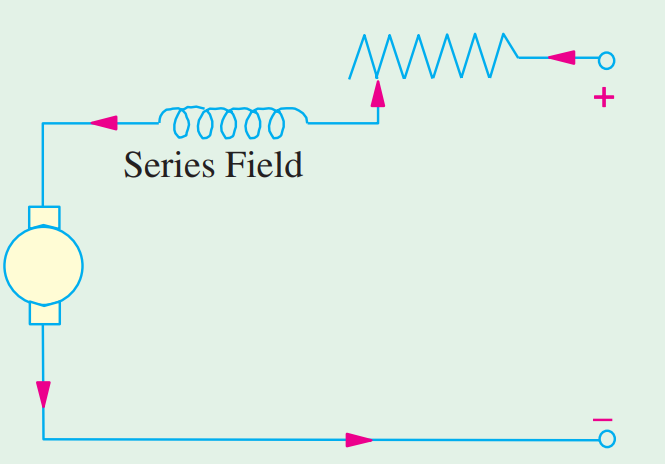
- With reduced voltage across the armature, the speed is reduced.
- However, since full motor current passes through this resistance, there is a considerable loss of power (\(i^2 R\)).
Speed and Direction of Permanent Magnet Motors
- For applications where speed and direction of permanent magnet DC motors (PMDCs) is required, these motors often form part of a more sophisticated electromechanical system.
- As such there is additional electronics, at least some of which is dedicated to the speed control of these PMDCs.
- A common control technique is to use a H-Bridge in combination with what is known as Pulse Width Modulation (PWM).
- H-Bridge is used for motor on/off and direction.
- PWM is used to control the speed.
H-Bridge
Interactive diagram: click a switch to close it and see the current path from \(V_s\) to ground · Open full screen ↗
- A H-Bridge configuration can be conceptualised as shown above.
- It consists of 4 switches (typically MOSFETs) arranged as shown.
- Each switch/combination of switches can be controlled via a microcontroller (\(\mu\)C) to facilitate current flow through the motor (\(M\)).
It should be noted that the current requirement for the motor is drawn from \(V_s\) as opposed to the \(\mu\)C. Typical \(\mu\)C outputs can deliver \(20 - 50\,\text{mA}\).
Clockwise rotation (SW1 and SW4 closed)
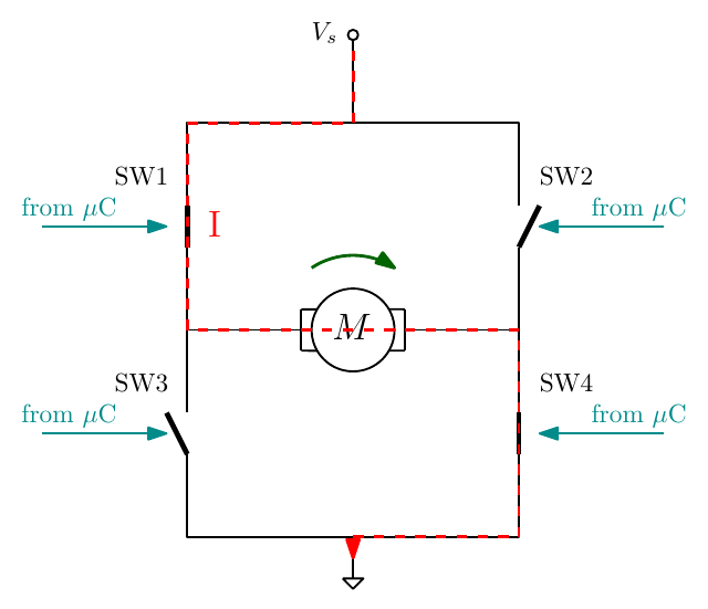
- In this configuration a signal from the microcontroller (Arduino/Teensy etc.) closes switches 1 and 4.
- This allows current flow from left to right through the motor and to ground, as indicated in red.
- For the purposes of explanation, this allows the motor to turn clockwise, as indicated in green.
Anti-clockwise rotation (SW2 and SW3 closed)
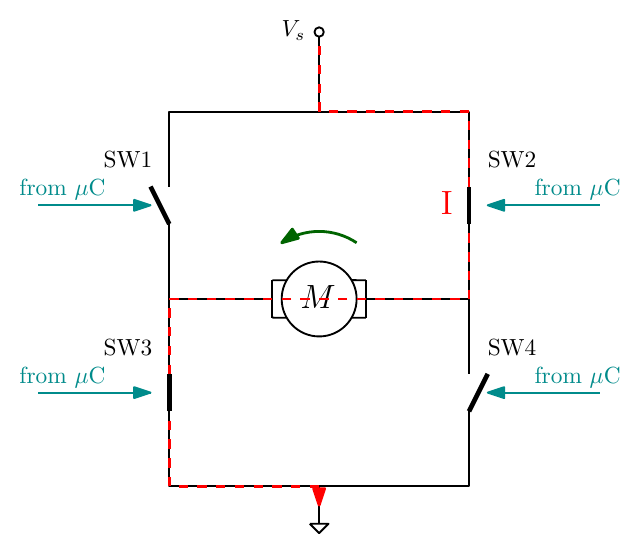
- In this configuration a signal from the microcontroller (Arduino/Teensy etc.) closes switches 2 and 3.
- This allows current flow from right to left through the motor and to ground, as indicated in red.
- For the purposes of explanation, this allows the motor to turn anti-clockwise, as indicated in green.
Pulse Width Modulation — PWM
- One method to control PMDC motor speed is to adjust the voltage supply \(V_s\). However most \(\mu\)Cs facilitate digital only outputs and at a much lower current.
- Pulse width modulation is a method of delivering a pseudo analog output from a microcontroller pin.
- At any instance in time the signal is digital high or low. Averaged over time, however, this signal can effectively be considered to vary.
Interactive diagram: drag the duty-cycle slider to see the waveform and average voltage change · Open full screen ↗
The duty cycle \(D\) is the fraction of each period \(T\) for which the signal is on, and the average (pseudo) voltage is that fraction of the high level:
\[ D = \frac{t_{\text{on}}}{T}, \qquad \bar{V} = D\,V_{\text{high}} \]
So a 66% duty cycle gives \(\bar{V} \approx 0.66\,V_{\text{high}}\) and a 20% duty cycle gives \(\bar{V} = 0.2\,V_{\text{high}}\).
H-Bridge with PWM
Interactive diagram: the PWM switch pulses in slow motion and the duty cycle sets the motor speed · Open full screen ↗
- Speed control of PMDC motors can be achieved through the use of PWM with a H bridge.
- A PWM signal is sent to a switch on the H bridge.
- The PWM duty cycle effectively controls the fraction of \(V_s\) across the motor:
\[ V_{\text{motor}} \approx D\,V_s \]
Example: L298N dual H-bridge motor driver
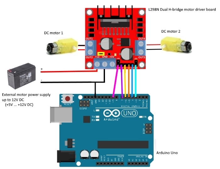
An L298N dual H-bridge motor driver board drives two DC motors (DC motor 1 and DC motor 2). The control pins come from an Arduino Uno, and the motor current comes from an external motor power supply (up to 12 V DC, +5 V to +12 V).
Alternative DC Motor Types
In the previous section we saw how electronic switching via a controller can enable speed control. Electronic switching is also key to enabling additional DC motor types. The two motor types we will look at are:
- Stepper motor
- Variable reluctance stepper
- Hybrid stepper
- Brushless DC motor
Stepper motors — What is a stepper?
- Controlled sequence of DC across coils
- Continuous rotation in forward or reverse
- Rotation in small steps
- Stepper motors can stop and hold rotation at defined positions
- Useful in automation and manufacturing
Stepper motor — Switching
- Motor requires a motor driver
- Driver consists of high speed electronic switches
- Controller tells the driver when and how to switch
- Each pulse can correspond to one step
Stepper motor — Principle of operation
- As with other DC motors, the stepper operation is based on interacting magnetic fields
- Sequential switching can energise and rotate the magnetic field
- Switching can be enabled via H-bridges
Stepper motor — Permanent magnet type
- Permanent magnet rotor
- Rotor aligns with opposing stator pole
- Stator poles and polarity are rotated via switching appropriate coils
Stepper motor — Variable reluctance type
- Soft iron magnet rotor.
- Rotor is not magnetic but is attracted to the magnetic field.
- Number of rotor teeth is different from the number of pole pairs.
- Rotor spins based on switching magnetic fields within the stator.
Stepper motor — Hybrid type
- Most common stepper
- Combination of magnetic and reluctance stepper
- Toothed, offset magnetic rotor enhances step resolution
Stepper motor — Stepper motor control
- Variety of control types
- Wave drive
- Full step
- Half step
- Micro step
Stepper motor simulator
Choose a permanent magnet, variable reluctance or hybrid rotor and a wave, full-step, half-step or microstep drive, then step the controller through its coil sequence and watch the rotor follow.
Interactive stepper motor · Open full screen ↗
Brushless DC motors
- Traditional brushes wear and can cause sparking
- BLDCs have an improved power to weight ratio
- Sequential switching of coils is analogous to three phase motors
- Can be driven with or without sensors
Brushless DC motor simulator
Six-step commutation from a three-phase inverter, with Hall sensor or sensorless (back-EMF) control.
Interactive brushless DC motor · Open full screen ↗
Comparison: Stepper vs BLDC motors
Choose what an application needs to see which motor suits it and why, or click any entry for the reason behind it.
Interactive comparison · Open full screen ↗
Knowledge Check
Q1. From \(N = K\dfrac{V_s - i_aR_a}{\Phi}\), name three ways to control the speed of a field-wound DC motor.
Answer
Varying the flux (flux control), the armature circuit resistance (rheostatic control), or the applied voltage (voltage control).
Q2. In flux control of a shunt motor, does reducing the field current increase or decrease the speed? Why is the method efficient?
Answer
It increases the speed, since \(N \propto 1/\Phi\). The field current is small, so the \(I_{sh}^2R\) loss in the field rheostat is small.
Q3. What is the main disadvantage of controlling a series motor’s speed with a resistance in series with the supply?
Answer
The full motor current passes through the resistance, so there is a considerable \(i^2R\) power loss.
Q4. What is the role of a field diverter in a series motor, and what does it do to the speed?
Answer
It is a variable resistance in parallel with the series field, diverting some of the current away from the field. This reduces the flux and so increases the speed.
Q5. In an H-bridge, which switches are closed to drive the motor one way, and which the other way? What must never happen?
Answer
SW1 and SW4 drive current left to right (clockwise); SW2 and SW3 drive it right to left (anticlockwise). SW1 and SW3 (or SW2 and SW4), on the same side, must never be closed together: that short-circuits the supply.
Q6. A 12 V supply is switched by PWM at 25% duty cycle. What average voltage does the motor see?
Answer
\(\bar{V} = D\,V_s = 0.25 \times 12 = 3\) V.
Q7. Why can’t a microcontroller drive a motor directly from its output pin?
Answer
Its outputs can only deliver small currents (typically 20–50 mA) and only digital (on/off) levels. A driver such as an H-bridge takes the motor current from \(V_s\), and PWM provides the variable average voltage.
Q8. How do the permanent magnet, variable reluctance and hybrid stepper motors differ?
Answer
Permanent magnet: a magnetised rotor aligns with the stator poles. Variable reluctance: a soft-iron, non-magnetised toothed rotor is pulled into the position of least reluctance; it has a different number of teeth from the stator poles. Hybrid: a toothed, offset magnetised rotor combining both, for higher step resolution; the most common type.
Q9. Give two advantages of a brushless DC motor over a brushed one.
Answer
Any two of: no brushes to wear or spark, so longer life; better power-to-weight ratio; higher efficiency; windings on the stator, so better heat dissipation; high speed and torque at high speed.
Q10. When would you choose a stepper motor over a BLDC motor?
Answer
For light loads and slow motion that must stop in exact positions using simple, cheap open-loop control, such as 3D printers, camera sliders and small positioning stages.