Boolean Algebra and Truth Tables
Chapter 2 · Part I: Logic Control Fundamentals · Sources: Lectures 1 and 2
2.1 Truth tables
From an automation perspective, a truth table shows the state of one or more outputs for every possible combination of inputs.
| In1 | In2 | In3 | Out1 | Out2 |
|---|---|---|---|---|
| 0 | 0 | 0 | 1 | 0 |
| 0 | 0 | 1 | 0 | 1 |
| ⋮ | ⋮ | ⋮ | ⋮ | ⋮ |
Values are usually 0 or 1 (decision by attributes). There are also “don’t care” states, covered in Chapter 3.
2.2 Design example: panel switch with lock
An on/off switch S controls a process P only when the lock L is in unlock mode.
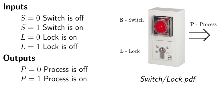
Figure 2.1: Panel switch with lock.
- Inputs: S = 0 switch off, S = 1 switch on; L = 0 lock on, L = 1 lock off
- Outputs: P = 0 process off, P = 1 process on
Account for every condition by counting up in binary. With many inputs this becomes cumbersome, so include only the inputs that are relevant.
- Only when the lock is off (L = 1) can S dictate the state of P.
- When the lock is on (L = 0), P stays unchanged, so the current state of P determines its future state.
- To complete the truth table, the output P must therefore also be included as an input.
\(P'\) is the process as an output (the new state); \(P\) is the process as an input (the previous state):
| S | L | P | P′ |
|---|---|---|---|
| 0 | 0 | 0 | 0 |
| 0 | 0 | 1 | 1 |
| 0 | 1 | 0 | 0 |
| 0 | 1 | 1 | 0 |
| 1 | 0 | 0 | 0 |
| 1 | 0 | 1 | 1 |
| 1 | 1 | 0 | 1 |
| 1 | 1 | 1 | 1 |
- Each row is considered in terms of its physical meaning, and the output is assigned accordingly.
- Rows 4 and 7 look like a paradox, since \(P' \ne P\). They make sense once you treat input \(P\) as the state of the output during the previous scan cycle of the program; the new output \(P'\) is calculated from it.
- When L = 0, \(P' = P\); when L = 1, \(P' = S\).
2.3 Design example: latching with Go and Stop buttons
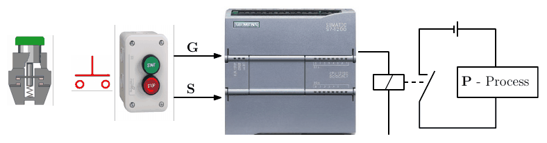
Figure 2.2: Go/Stop latching circuit.
Inputs: G = 0/1 Go button not pressed/pressed; S = 0/1 Stop button not pressed/pressed.
- The Stop button takes precedence over the Go button.
- Once Go is pressed, the system latches on until Stop is pressed.
| G | S | P | P′ |
|---|---|---|---|
| 0 | 0 | 0 | 0 |
| 0 | 0 | 1 | 1 |
| 0 | 1 | 0 | 0 |
| 0 | 1 | 1 | 0 |
| 1 | 0 | 0 | 1 |
| 1 | 0 | 1 | 1 |
| 1 | 1 | 0 | 0 |
| 1 | 1 | 1 | 0 |
If S = 1 then \(P' = 0\); if S = 0 then \(P' = P + G\).
2.4 Basic gates
Truth tables are evaluated using Boolean algebra, which has three basic operators.
| A | B | AND \(A.B\) | OR \(A + B\) | NOT \(\overline{A}\) |
|---|---|---|---|---|
| 0 | 0 | 0 | 0 | 1 |
| 0 | 1 | 0 | 1 | 1 |
| 1 | 0 | 0 | 1 | 0 |
| 1 | 1 | 1 | 1 | 0 |
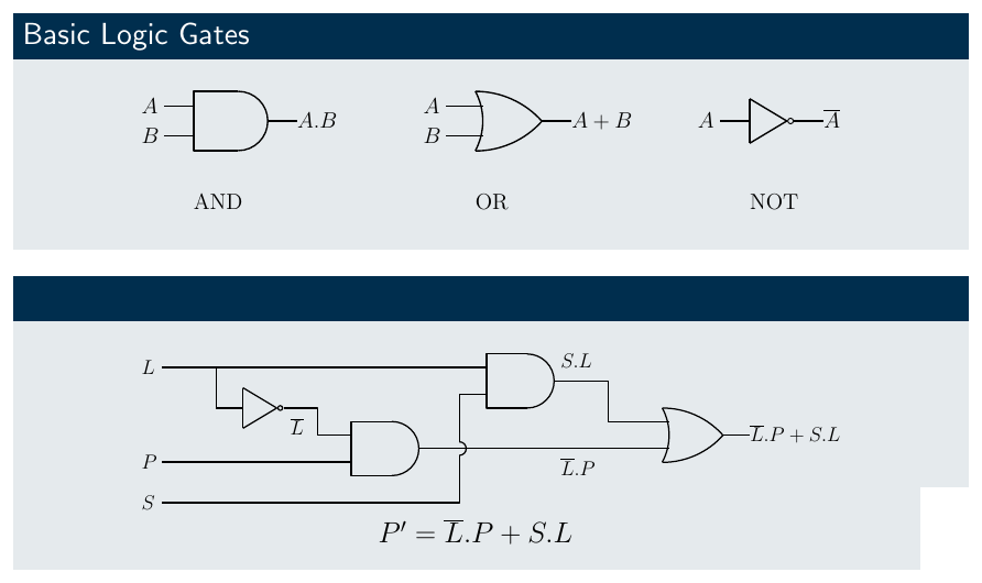
Figure 2.3: Gate symbols (top) and the switch-with-lock circuit (bottom), revisited in Chapter 4.
2.5 Truth table reduction (sum of products)
Taking the switch with lock:
- The output is on when \(P' = 1\).
- Each row is written as a product term: an input appears directly if it is 1 and negated (barred) if it is 0.
- The output is on if any row with output 1 is true, so these rows are combined with OR (+), and the variables within each row with AND (.).
Taking only the rows where the output is on:
\[P' = \overline{S}.\overline{L}.P + S.\overline{L}.P + S.L.\overline{P} + S.L.P\]
This expression can be simplified using the laws below.
2.6 Boolean theorems and laws
| Name | Rules |
|---|---|
| Characteristic | \(X.0 = 0\); \(X.1 = X\); \(X + 0 = X\); \(X + 1 = 1\) |
| Negation | \(\overline{\overline{X}} = X\) |
| Inclusion | \(X.\overline{X} = 0\); \(X + \overline{X} = 1\) |
| Commutative | \(X + Y = Y + X\); \(X.Y = Y.X\) |
| Associative | \(X + Y + Z = X + (Y + Z) = (X + Y) + Z\); \(X.Y.Z = X.(Y.Z) = (X.Y).Z\) |
| Distributive | \(X.Y + X.Z = X.(Y + Z)\); \((X + Y).(W + Z) = X.W + X.Z + Y.W + Y.Z\) |
| Idempotent | \(X.X = X\); \(X + X = X\) |
| Absorptive | \(X + X.Y = X\); \(X.(X + Y) = X\) |
| Reflective | \(X + \overline{X}.Y = X + Y\); \(X.(\overline{X} + Y) = X.Y\); \(X.Y + \overline{X}.Y.Z = X.Y + Y.Z\) |
| Consistency | \(X.Y + X.\overline{Y} = X\); \((X + Y).(X + \overline{Y}) = X\) |
| De Morgan | \(\overline{X.Y} = \overline{X} + \overline{Y}\); \(\overline{X + Y} = \overline{X}.\overline{Y}\) |
2.7 Solving the switch-with-lock expression
\[P' = \overline{S}.\overline{L}.P + S.\overline{L}.P + S.L.\overline{P} + S.L.P\]
Distributive law: \[P' = (\overline{S} + S).\overline{L}.P + S.L.(\overline{P} + P)\]
Inclusion theorem: \[P' = (1).\overline{L}.P + S.L.(1)\]
Characteristic theorem: \[\boxed{P' = \overline{L}.P + S.L}\]
This matches the physical reasoning: with the lock on, P holds its state; with the lock off, P follows S.
Key points
- Feeding the output back as an input (\(P \to P'\)) models memory across PLC scan cycles.
- Sum-of-products: OR together the rows where the output is 1, each written as an AND of its inputs.
- Boolean laws reduce the expression to the minimum number of contacts or gates.
Interactive applets
Each applet runs in the page; use Open full screen for more room, or open all of this chapter’s applets together.
Applet 2.1 · Truth table builder
Name inputs and outputs, then click output cells to toggle 0/1/X. The applet generates the sum-of-products expression live.
Teaches: Systematic enumeration (binary counting) and sum-of-products. · Open full screen ↗
Applet 2.2 · Scan-cycle stepper (switch with lock)
Flip S and L, press “Next scan”, and watch \(P\) (previous) become \(P'\) (new) with the active truth-table row highlighted.
Teaches: Why the output must also be an input, and why rows 4 and 7 aren’t a paradox. · Open full screen ↗
Applet 2.3 · Gate playground
Wire AND, OR and NOT gates on a canvas with clickable input switches and lamp outputs.
Teaches: Gate behaviour, and how a feedback wire creates a latch. · Open full screen ↗
Applet 2.4 · Boolean simplifier with step-by-step laws
Type an expression; the applet suggests which law to apply at each step and checks the result against a truth table.
Teaches: Practice using the theorem table; equivalence checking. · Open full screen ↗