Automatic Assembly and Transfer Systems
Chapter 13 · Part IV: Automated Assembly and Parts Feeding · Source: Lecture 11
13.1 Automatic assembly
This part of the course covers transfer systems; parts feeding (mechanisms, orientation, tracks and escapements); performance assessment; and cost justification.
Reasons for automating include:
- Reduce cost
- Increase productivity
- Improve consistency and quality
- Remove operators from hazardous environments and operations
Historical context
Automatic assembly was needed to keep up with mass production; previously a complete product was made by one craftsman.
- 1793: Oliver Evans developed conveyor systems in a mill.
- 1798: E. R. (Eli) Whitney tendered to make 10,000 muskets in 28 months. He produced interchangeable parts on machines, which gave simpler assembly, better quality and a lower price (although the contract took 10.5 years!).
- Frederick Winslow Taylor introduced time and motion studies, examining the best positioning of tools and components relative to the worker, and an optimum work speed not to be exceeded.
- Henry Ford automated car assembly with a conveyor system and attention to production-line ergonomics, cutting the production time from 12 h 28 min to 10 s (as quoted on the slide).
13.2 Transfer systems
Transfer systems move the workpiece between separate workstations. Usually the workpiece sits on a base or work carrier.
| Classification | Options |
|---|---|
| Topology | In-line: workstations arranged in a line · Rotary: workstations around a central point (usually at most six) |
| Motion | Continuous: the workhead moves with the transfer system, so acceleration, deceleration and accuracy are key · Intermittent: the workhead stays stationary and the workpiece moves intermittently |
When all workheads or workpieces move simultaneously, the system is an indexing machine.
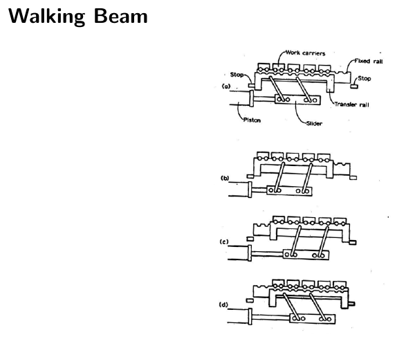
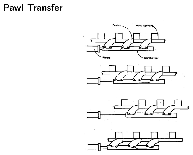
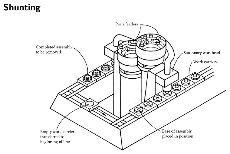
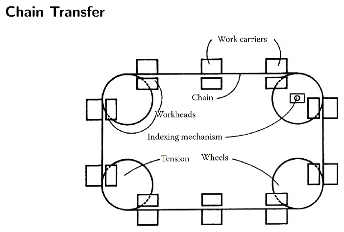
In-line intermittent transfer
| Walking beam | Pawl transfer |
|---|---|
 |
 |
| Shunting | Chain transfer |
 |
 |
Rotary intermittent transfer
Intermittent translation converted to intermittent rotation, e.g. a pneumatic piston driving a rack and pinion with a one-way clutch, or a piston driving a ratchet and pawl:
| Rack and pinion with one-way clutch | Ratchet and pawl |
|---|---|
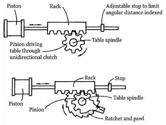 |
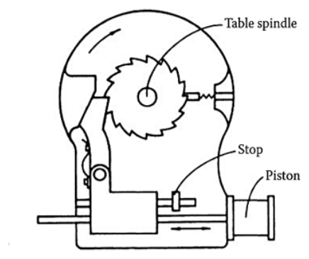 |
Continuous rotation converted to intermittent rotation: the Geneva mechanism.

Figure 13.1: Geneva mechanism. The driver’s pin enters a slot in the driven member and indexes it one station per revolution.
13.3 The Geneva mechanism
- More expensive than pneumatic piston drives
- Can transmit higher torques
- Quite prone to wear: lubricate it, and set the distance between the centres of the driving and driven wheels carefully
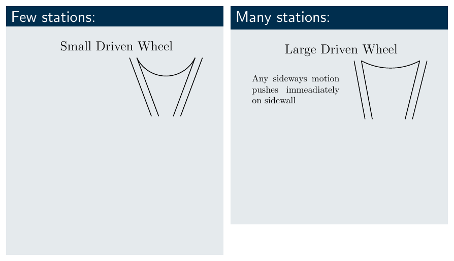
Figure 13.2: Slot geometry for few vs many stations.
| Few stations (small driven wheel) | Many stations (large driven wheel) |
|---|---|
| Sideways motion is partly accommodated by the larger slot angle. The driven member’s relative speed is high and, at fixed power, torque is low, especially mid-transfer when the pin is closest to the driven wheel’s centre. This gives a very peaked acceleration profile. | Any sideways motion pushes immediately on the slot sidewall. The pin enters the slot with a higher velocity perpendicular to it, giving greater acceleration at the start and end of the transfer phase. |
Worked example: index and dwell time
An indexing table driven by a Geneva mechanism has six stations and a driver speed of 12 rpm. Calculate the indexing time and the dwell time.
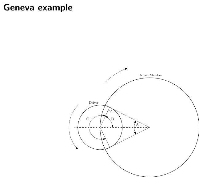
Figure 13.3: Angles A (between slots), B (half the driver’s indexing angle) and C (the driver’s dwell angle).
Since the pin enters the slot at a right angle:
\[0.5A + B + 90^\circ = 180^\circ \;\Rightarrow\; 0.5A + B = 90^\circ \qquad 2B + C = 360^\circ\]
\[\text{Index time} = \frac{2B/360^\circ}{n} \qquad \text{Dwell time} = \frac{C/360^\circ}{n}\]
where \(n\) is the driver speed.
- \(A = 360^\circ/6 = 60^\circ\)
- \(B = 90^\circ - 30^\circ = 60^\circ\)
- \(C = 360^\circ - 120^\circ = 240^\circ\)
\[\text{Index time} = \frac{120^\circ/360^\circ}{12} = 0.0278\ \text{min} = 1.67\ \text{s}\] \[\text{Dwell time} = \frac{240^\circ/360^\circ}{12} = 0.0556\ \text{min} = 3.33\ \text{s}\]
(Check: 1.67 + 3.33 = 5 s = one driver revolution at 12 rpm.)
In general, for an \(N\)-station Geneva: \(A = 360^\circ/N\), \(2B = 180^\circ - 360^\circ/N\), and \(C = 180^\circ + 360^\circ/N\).
13.4 The cross-over cam
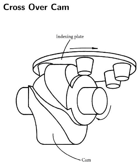
Figure 13.4: Cross-over cam.
- Can provide high torque
- Accurate and consistent
- Relatively bulky and expensive to manufacture
The acceleration profile depends on the cam shape. Three profiles are used: sine, modified sine (better) and modified trapezoid (best).
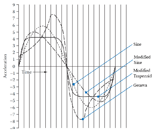
Figure 13.5: Acceleration profiles compared with a Geneva mechanism.
13.5 Choosing an indexing machine
- Required lifetime: a larger machine lasts longer.
- Dynamic torque: the torque needed to move a fully loaded machine, allowing for all inertia and friction forces, plus extra capacity for ageing and wear.
- Static torque: the torque needed to withstand forces from the workheads. If dowels or locating plungers are used it is negligible, and the power requirement is set by the dynamic torque.
- Power source: single-phase, three-phase, pneumatic or hydraulic.
- Acceleration pattern: to minimise cycle time the transfer phase should be as short as possible, but very high acceleration causes excessive loads, so a smooth acceleration profile is preferred to prolong the machine’s life.
Pacing
- In the transfer machines described so far, a malfunction at any one workstation stops the whole machine, and every operation must finish within a set time: machine pacing.
- If the system only indexes when told to by feedback from the individual stations: operator pacing.
- Placing storage buffers between stations makes each station somewhat independent of the others, improving flexibility: free transfer machines (analysed in Chapter 18).
Key points
- Transfer systems are in-line or rotary, and continuous or intermittent; an indexing machine moves everything at once.
- Geneva: index time \(= (2B/360^\circ)/n\), dwell time \(= (C/360^\circ)/n\); it suits high torque but wears.
- Cam indexers give smoother, designable motion; the modified trapezoid profile is best.
Interactive applets
Each applet runs in the page; use Open full screen for more room, or open all of this chapter’s applets together.
Applet 13.1 · Geneva mechanism simulator
Choose the number of stations (3–12) and driver speed; an animated Geneva rotates while live plots show driven-wheel angle, velocity and acceleration, with index and dwell times calculated.
Teaches: The worked example, and the few- vs many-station acceleration behaviour. · Open full screen ↗
Applet 13.2 · Cam profile comparator
Overlay the sine, modified sine, modified trapezoid and Geneva acceleration curves; adjust the index period and payload inertia to see peak acceleration, torque and jerk.
Teaches: Why the modified trapezoid is preferred. · Open full screen ↗
Applet 13.3 · Transfer mechanism gallery
Animated walking beam, pawl, shunting and chain transfer, with step-through controls.
Teaches: How each in-line method moves carriers. · Open full screen ↗
Applet 13.4 · Pacing playground
A 5-station line toggles between machine-paced, operator-paced and free transfer (with buffers); random station faults show how far each stoppage propagates.
Teaches: Leads into the performance analysis in Chapter 18. · Open full screen ↗