Microcontrollers Part 8 — Renewable source with battery backup
The system
Everything from Parts 1–7 comes together:
| Part | Used for |
|---|---|
| Voltage divider (Part 5) | Scale the RES voltage into the 0–5 V range of an analogue pin |
analogRead and if/else thresholds (Part 6) |
Decide whether the RES voltage is high enough |
| Relays (Part 7) | Connect the load to either the RES or the battery |
Goal: power the load from the renewable energy source (RES) whenever it is producing enough voltage, and switch automatically to the battery backup when the RES voltage drops.
Step 1 — power and signals from Arduino to relay
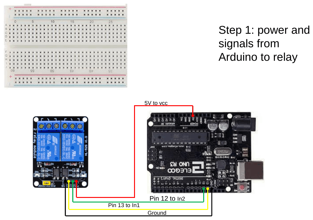
| Arduino | Relay module | Purpose |
|---|---|---|
| 5 V | VCC | Powers the relay coils / opto-isolators |
| GND | GND | Common ground |
| Pin 13 | IN1 | Controls the battery relay |
| Pin 12 | IN2 | Controls the RES relay |
Step 2 — RES power in through the relay
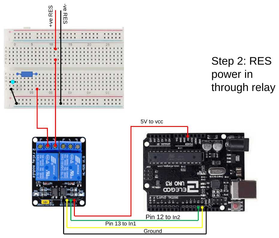
- +ve RES → COM of the RES relay.
- The relay’s NO output → the breadboard supply rail that feeds the load (here an LED + resistor stands in for the pump).
- −ve RES → breadboard ground rail.
Step 3 — battery power in through the relay
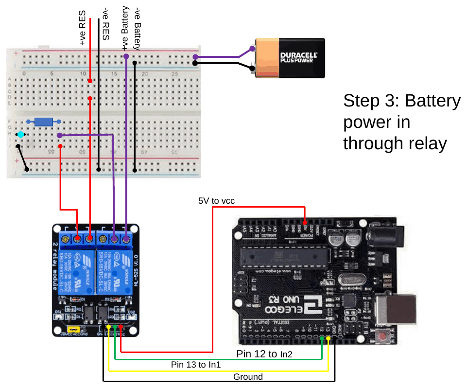
- +ve battery → COM of the battery relay; its NO output joins the same load supply rail.
- −ve battery → ground rail.
Only one relay is energised at a time, so the load is fed from one source or the other — never both.
Step 4 — add the monitoring system
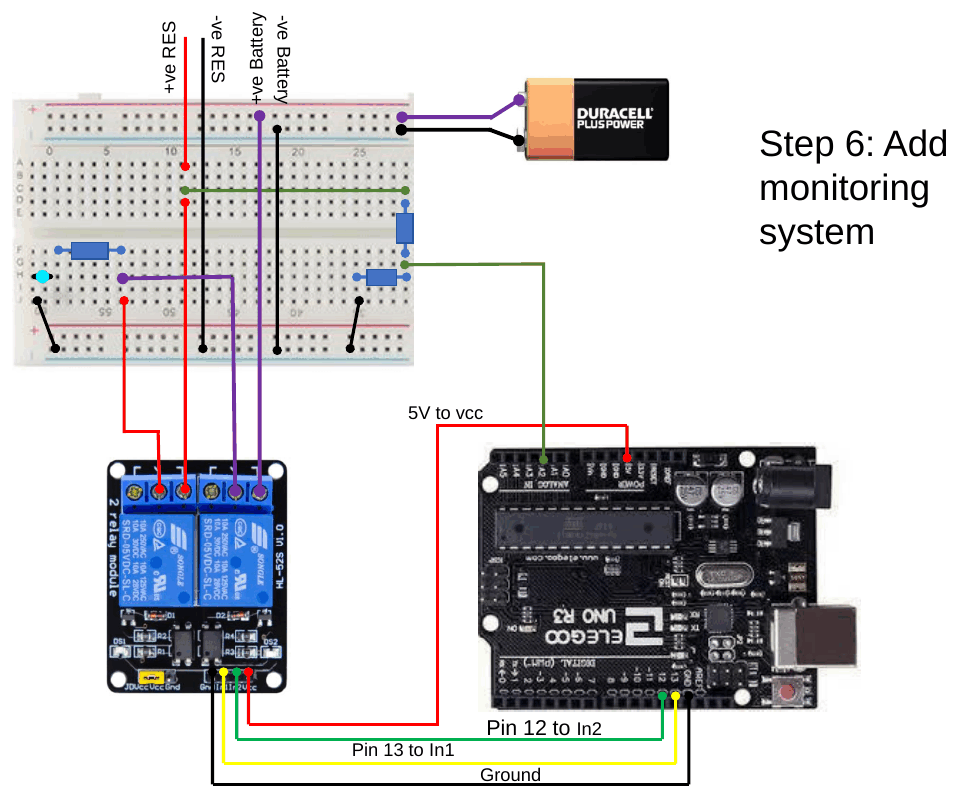
- A voltage divider (two resistors in series) across the RES output.
- The mid-point of the divider → Arduino analogue input (A2 in the code below).
- Size the resistors with \(R_1 = \left(\frac{V_{max}}{5} - 1\right)R_2\) so the maximum RES voltage gives ≤ 5 V at the pin — see Part 5.
Step 5 — don’t forget to ground
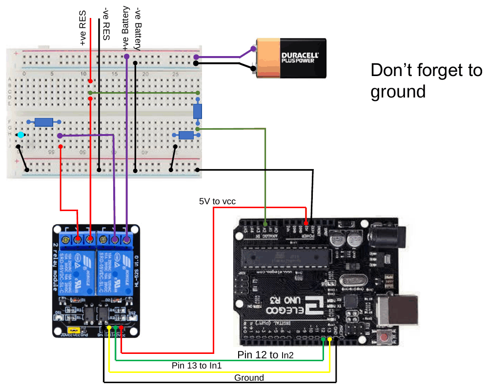
The Arduino GND must be connected to the RES/battery ground rail. A voltage is always measured relative to something — without a shared ground, the Arduino’s analogRead has no reference and returns meaningless values.
Code
/*
 * Monitor the voltage from a renewable energy source (RES) and switch the
 * load to the backup battery when that voltage drops.
 * Hardware: divider mid-point -> A2; D12 -> IN2 (RES relay);
 *           D13 -> IN1 (battery relay); 5 V -> VCC; all grounds joined.
 */

const uint8_t  kResPin      = A2;      // divider mid-point (scaled RES voltage)
const uint8_t  kResRelay    = 12;      // relay that connects the RES to the load
const uint8_t  kBatRelay    = 13;      // relay that connects the battery to the load
const float    kThresholdV  = 2.5;     // below this (at the pin) the RES is "too low"
const float    kAdcVref     = 5.0;     // analogRead reference voltage (V)
const float    kAdcMax      = 1023.0;  // largest analogRead value
const uint16_t kSampleMs    = 100;     // time between readings (ms)
const uint8_t  kRelayOn     = LOW;     // the relay module is active-LOW
const uint8_t  kRelayOff    = HIGH;

// Read an analogue pin and return the voltage on it (0 to 5 V).
float readVolts(uint8_t pin) {
  return analogRead(pin) * (kAdcVref / kAdcMax);
}

// Power the load from the RES. The battery is disconnected first.
void useRes() {
  digitalWrite(kBatRelay, kRelayOff);
  digitalWrite(kResRelay, kRelayOn);
}

// Power the load from the battery. The RES is disconnected first.
void useBattery() {
  digitalWrite(kResRelay, kRelayOff);
  digitalWrite(kBatRelay, kRelayOn);
}

void setup() {
  Serial.begin(9600);
  digitalWrite(kResRelay, kRelayOff);    // both relays off until we decide
  digitalWrite(kBatRelay, kRelayOff);
  pinMode(kResRelay, OUTPUT);
  pinMode(kBatRelay, OUTPUT);
  useRes();                              // start on the renewable source
}

void loop() {
  float vPin = readVolts(kResPin);       // scaled-down RES voltage at the pin
  Serial.println(vPin);

  if (vPin < kThresholdV) {
    useBattery();                        // RES voltage has dropped
  } else {
    useRes();                            // RES is fine
  }

  delay(kSampleMs);
}
Run it: the switch-over sketch in the code runner — drag the A2 voltage below 2.5 V and watch the load move to the battery. · Open full screen ↗
How it works
setup()makes sure both relays start off, then connects the RES.- Each pass of
loop()reads the divider voltage withreadVolts()and prints it. - If the pin voltage is below 2.5 V the load is switched to the battery; otherwise it stays on the RES.
Explainer: the two helper functions
useRes()anduseBattery()each describe a whole action in one name, soloop()reads like the specification: “if the voltage is low, use the battery, otherwise use the RES”.- Off before on. Each function disconnects the old source before connecting the new one. If both relays were on at the same moment, the RES and the battery would be connected directly together, and current could flow from one into the other.
- Active-LOW is hidden in two constants.
kRelayOn = LOWandkRelayOff = HIGHare the only place the module’s back-to-front logic appears. readVolts()is the same helper used in Parts 6 and 7.
💡 Compared with the slide: pin numbers are
const uint8_t(the slide usedfloat RESval = A2;), the threshold is a named constant, and the relays are switched off before the new source is connected.
What does 2.5 V at the pin mean at the source?
\[V_{RES} = \frac{V_{pin}}{R_2/(R_1+R_2)}\]
With two equal resistors the threshold is 5 V at the RES; with \(R_1 = 2.172R_2\) (Part 5’s 15.86 V design) it is \(2.5 \times 3.172 \approx 7.9\ \text{V}\). Choose the threshold to match the minimum useful voltage for your load.
Improvement: hysteresis
If the RES voltage hovers right at the threshold (e.g. a gusty wind turbine), the relays will chatter on and off rapidly, wearing them out. Use two thresholds. Replace loop() in the sketch above with:
const float kToBatteryV = 2.3;   // switch to the battery below this
const float kToResV     = 2.7;   // switch back to the RES only above this

void loop() {
  float vPin = readVolts(kResPin);
  Serial.println(vPin);

  if (vPin < kToBatteryV) {
    useBattery();                // clearly too low
  } else if (vPin > kToResV) {
    useRes();                    // clearly recovered
  }
  // Between 2.3 and 2.7 V neither branch runs, so the relays stay as they are.

  delay(kSampleMs);
}
Explainer: why two thresholds stop the chatter
- With one threshold at 2.5 V, a reading that wobbles 2.49 → 2.51 → 2.49 flips the relays every time.
- With two thresholds there is a dead band from 2.3 V to 2.7 V. Inside it,
loop()does nothing, so the load stays on whichever source it already had. The voltage has to fall clearly (below 2.3 V) to switch to the battery, and recover clearly (above 2.7 V) to switch back. - This is the same idea as a home thermostat, which doesn’t switch the heating on and off at exactly one temperature.
Try it: RES battery-backup simulator — tick “Gusty”, put the wind around the threshold and watch the relays switch; then think about how hysteresis would help. · Open full screen ↗
Key points
- Relays select the source; the divider +
analogReadmeasure the RES; anif/elsedecides. - The relay module is active-LOW: LOW = connected.
- Always share ground between the Arduino and the power circuits.
- Translate the pin threshold back to a source voltage using the divider ratio.