Microcontrollers Part 7 — Relays
Learning outcomes
- Understand how relays work
- Understand and apply relays to change signal (power) sources
1. The relay module
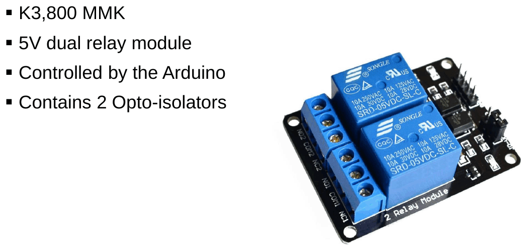
- 5 V dual relay module — two independent relays on one board (cost on the slide: K3,800 MMK — they are cheap and widely available).
- Controlled by the Arduino — a digital pin decides whether each relay is on or off.
- Contains 2 opto-isolators — the Arduino’s signal drives an LED inside the opto-isolator, which switches the relay driver. The Arduino is therefore optically (not electrically) connected to the relay coil, protecting it from voltage spikes.
Control side vs operating side
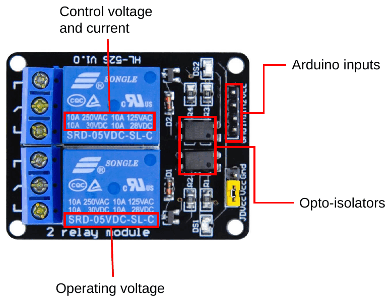
| Side | Pins | Connects to |
|---|---|---|
| Control (low-voltage) side | VCC, GND, IN1, IN2 |
Arduino 5 V, GND and two digital pins |
| Operating (switched) side | Screw terminals for each relay: NC, COM, NO |
The power circuit being switched (RES, battery, load) |
The relay contacts on these modules are rated up to 10 A at 250 VAC / 30 VDC, far beyond anything an Arduino pin (≈ 20 mA) could switch directly.
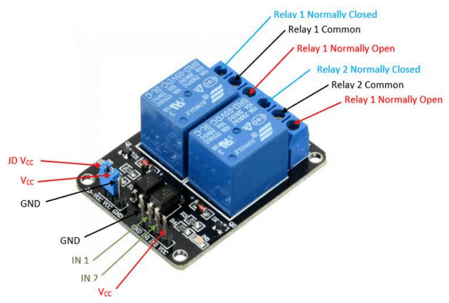
The jumper between JD-VCC and VCC lets the relay coils share the Arduino’s 5 V supply; leave it in place for this course.
2. Relay mechanism
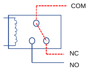
Inside each relay is an electromagnet (coil) and a switch arm:
| Terminal | Meaning |
|---|---|
| COM | Common — the moving contact; wire your power source here |
| NC | Normally Closed — connected to COM when the relay is off (coil not energised) |
| NO | Normally Open — connected to COM only when the relay is on (coil energised) |
| Relay off (de-energised): COM → NC | Relay on (energised): COM → NO |
|---|---|
 |
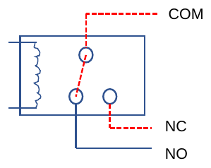 |
When the coil is energised, its magnetic field pulls the arm from NC across to NO — you hear a click and the module’s indicator LED lights.
3. Switching a load
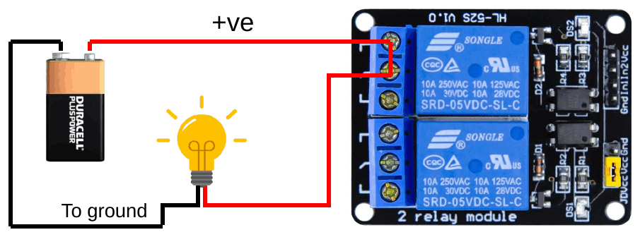
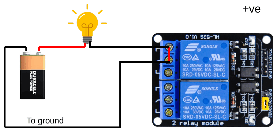
To switch a lamp (or pump, or LED) from a battery:
- Battery +ve → COM
- NO → load → ground (battery −ve)
The lamp then lights only when the relay is energised. Wire to NC instead if you want the load on by default and switched off by the Arduino.
 |
 |
⚠️ Active-LOW inputs. On most of these blue opto-isolated modules a LOW on
IN1/IN2turns the relay ON, and HIGH turns it off. The Part 8 and final-circuit code relies on this (it writes LOW to the relay it wants to connect). Test yours: upload Example 3a and watch which state lights the module LED.
Try it: Relay simulator — switch between active-LOW and active-HIGH and between NO/NC wiring. · Open full screen ↗
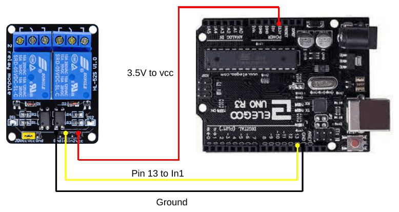
4. Example 3a — open and close relay 1
| Arduino | Relay module |
|---|---|
| 5 V | VCC |
| GND | GND |
| Pin 13 | IN1 |
⚠️ The circuit slides label the supply wire “3.5V to vcc”. The Arduino has no 3.5 V pin, and the relay coils (SRD-05VDC) are rated at 5 V — connect VCC to the 5 V pin, as the Part 8 slides do.
/*
 * Example 3a: Switch relay 1 on and off every second.
 * Hardware: Arduino 5 V -> VCC, GND -> GND, D13 -> IN1 on the relay module.
 */

const uint8_t  kRelay1Pin = 13;      // Arduino pin 13 drives IN1
const uint16_t kSwitchMs  = 1000;    // time in each state (ms)

// The relay module is active-LOW: LOW switches a relay on, HIGH switches it off.
const uint8_t  kRelayOn   = LOW;
const uint8_t  kRelayOff  = HIGH;

void setup() {
  digitalWrite(kRelay1Pin, kRelayOff);   // choose "off" before the pin becomes an output
  pinMode(kRelay1Pin, OUTPUT);
}

void loop() {
  digitalWrite(kRelay1Pin, kRelayOn);    // relay energised: COM connects to NO (click)
  delay(kSwitchMs);
  digitalWrite(kRelay1Pin, kRelayOff);   // relay released: COM back to NC (click)
  delay(kSwitchMs);
}
Run it: Example 3a in the code runner — watch kRelayOn (LOW) switch the relay on. · Open full screen ↗
Explainer: active-LOW and a clean start
kRelayOn = LOWandkRelayOff = HIGHgive names to the module’s back-to-front logic. The rest of the code then reads naturally (kRelayOn,kRelayOff), and if you swap to an active-HIGH module you only change these two lines.digitalWritebeforepinMode: when the board starts, pins are inputs. WritingHIGHfirst and then making the pin an output means it goes straight to “off”. Doing it the other way round briefly outputsLOW, which on this module would click the relay on for an instant at every reset.
5. Exercise 3b — alternate relay 1 and relay 2
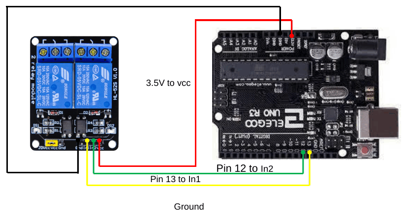
Add pin 12 → IN2.
/*
 * Exercise 3b: Alternate between relay 1 and relay 2.
 * Relay 1 on for 0.5 s, then relay 2 on for 1 s, and repeat.
 * Hardware: D13 -> IN1, D12 -> IN2, 5 V -> VCC, GND -> GND.
 */

const uint8_t  kRelay1Pin = 13;      // drives IN1
const uint8_t  kRelay2Pin = 12;      // drives IN2
const uint16_t kRelay1Ms  = 500;     // time with relay 1 on (ms)
const uint16_t kRelay2Ms  = 1000;    // time with relay 2 on (ms)
const uint8_t  kRelayOn   = LOW;     // active-LOW module
const uint8_t  kRelayOff  = HIGH;

void setup() {
  digitalWrite(kRelay1Pin, kRelayOff);   // both relays off at start-up
  digitalWrite(kRelay2Pin, kRelayOff);
  pinMode(kRelay1Pin, OUTPUT);
  pinMode(kRelay2Pin, OUTPUT);
}

void loop() {
  digitalWrite(kRelay2Pin, kRelayOff);   // relay 2 off first ...
  digitalWrite(kRelay1Pin, kRelayOn);    // ... then relay 1 on
  delay(kRelay1Ms);

  digitalWrite(kRelay1Pin, kRelayOff);   // relay 1 off first ...
  digitalWrite(kRelay2Pin, kRelayOn);    // ... then relay 2 on
  delay(kRelay2Ms);
}
Run it: Exercise 3b in the code runner — see each relay switched off before the other comes on. · Open full screen ↗
Explainer
- Names that match the wiring:
kRelay1Pindrives IN1 andkRelay2Pindrives IN2. The slide’sR1pin = 12actually drove IN2, which is an easy way to wire something wrong. - Off before on (break before make): each change switches the old relay off before switching the new one on. With LEDs it makes no difference, but when the relays switch two power sources (Part 8), it stops the two sources ever being connected together, even for a moment.
6. Exercise 3c — switch an LED through relay 1
Add a blue LED to the circuit in R1 and programme the MC to switch it on and off.
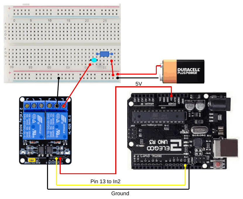
- A separate battery powers the LED circuit; its +ve goes to COM of relay 1.
- NO of relay 1 → resistor → blue LED → battery −ve.
- The Arduino code from Example 3a now switches the LED — but the LED’s power comes from the battery, not the Arduino.
7. Exercise 3d — alternate two LEDs
Add a green LED to the relay and alternate between the R1 LED and the R2 LED.
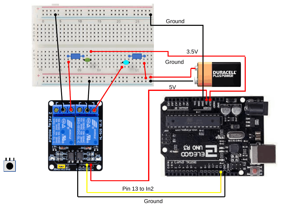
Wire the green LED through relay 2 the same way, then use the Exercise 3b code — the LEDs alternate as the relays alternate.
8. Exercise 3e — potentiometer control
Add a potentiometer to turn on the green LED below 2.5 V and turn it off above 2.5 V, and turn on the blue LED.
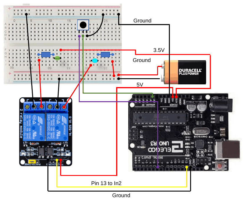
This combines Part 6 (read the pot, compare with 2.5 V) and Part 7 (drive relays):
/*
 * Exercise 3e: The potentiometer chooses which relay is on.
 * Below 2.5 V: relay 2 on (green LED). At or above 2.5 V: relay 1 on (blue LED).
 * Hardware: pot wiper -> A1; D13 -> IN1 (blue LED circuit);
 *           D12 -> IN2 (green LED circuit); 5 V -> VCC, GND -> GND.
 */

const uint8_t  kPotPin     = A1;      // pot wiper
const uint8_t  kBlueRelay  = 13;      // IN1: switches the blue LED
const uint8_t  kGreenRelay = 12;      // IN2: switches the green LED
const float    kThreshold  = 2.5;     // switching voltage (V)
const float    kAdcVref    = 5.0;
const float    kAdcMax     = 1023.0;
const uint16_t kSampleMs   = 100;
const uint8_t  kRelayOn    = LOW;     // active-LOW module
const uint8_t  kRelayOff   = HIGH;

float readVolts(uint8_t pin) {
  return analogRead(pin) * (kAdcVref / kAdcMax);   // reading -> volts
}

// Switch a relay on (true) or off (false), hiding the active-LOW detail.
void setRelay(uint8_t pin, bool on) {
  digitalWrite(pin, on ? kRelayOn : kRelayOff);
}

void setup() {
  Serial.begin(9600);
  digitalWrite(kBlueRelay, kRelayOff);    // both off at start-up
  digitalWrite(kGreenRelay, kRelayOff);
  pinMode(kBlueRelay, OUTPUT);
  pinMode(kGreenRelay, OUTPUT);
}

void loop() {
  float vOut = readVolts(kPotPin);
  Serial.println(vOut);

  if (vOut < kThreshold) {
    setRelay(kBlueRelay, false);          // off first ...
    setRelay(kGreenRelay, true);          // ... then on: green LED lit
  } else {
    setRelay(kGreenRelay, false);
    setRelay(kBlueRelay, true);           // blue LED lit
  }

  delay(kSampleMs);
}
Run it: Exercise 3e in the code runner — move the pot either side of 2.5 V and follow setRelay(). · Open full screen ↗
Explainer
setRelay(pin, true)means “relay on” whatever the module’s logic. The function turnstrue/falseintokRelayOn/kRelayOffusing the ternary operator (on ? kRelayOn : kRelayOff), so the rest of the program never has to remember that LOW means on.readVolts()is the same helper used in Part 6.- This is the full Part 8 system in miniature: a measured voltage, compared with a threshold, decides which relay is on.
Replace the pot with the divider output from a renewable source and the LEDs with the RES and battery supplies, and you have the final project — see Part 8.
Key points
- A relay lets a low-power Arduino signal switch a separate, higher-power circuit.
- COM is the moving contact; NC is connected when off; NO is connected when on.
- Control side: VCC (5 V), GND, IN1, IN2. Operating side: the screw terminals.
- These modules are usually active-LOW — check before relying on HIGH = on.