PLC Programming: Sequence Control, Logic Control and Staged Programs
Chapter 8 · Part II: Programmable Logic Controllers · Sources: Lectures 6, 7 and 8
8.1 Two ways to program a PLC
| Logic control | Sequencing | |
|---|---|---|
| How a step ends | A sensor switches on completion of each step, changing a PLC input; the PLC processes the new inputs and changes the outputs | Internal timers calculate the completion time of the current step and trigger the next |
| Loop type | Closed loop (needs sensor feedback) | Open loop |
| Step duration | Each step takes only the minimum time needed | Needs a safety margin on every step |
| Confirmation | Ensures the previous step is complete before moving on | Assumes it is complete |
| Hardware | Needs feedback sensors | No feedback sensors |
Many PLCs also offer timing, counting, A/D conversion etc. Each PLC type has its own features, described in its operating and programming manual.
8.2 Sequence control of a machine tool
A workpiece is loaded onto a machine tool, machined and unloaded: eight operations A–H, analysed with a Multiple Activity Chart (also called a Cycle Layout).
| Task | Operation |
|---|---|
| A | Load |
| B | Clamp |
| C | Coolant on |
| D | Spindle on |
| E | Tool advance |
| F | Machine |
| G | Tool retract |
| H | Unload |
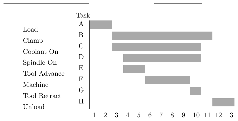
Figure 8.1: Multiple activity chart (time in seconds across the bottom).
In sequence programming, a new step starts every time something changes, i.e. one or more activities begin or end. Operations A–H are set by the PLC outputs, and the sequence is organised into steps with a matrix:
| Step | Time (s) | A | B | C | D | E | F | G | H |
|---|---|---|---|---|---|---|---|---|---|
| 1 | 2 | 1 | 0 | 0 | 0 | 0 | 0 | 0 | 0 |
| 2 | 1 | 0 | 1 | 1 | 0 | 0 | 0 | 0 | 0 |
| 3 | 2 | 0 | 1 | 1 | 1 | 1 | 0 | 0 | 0 |
| 4 | 4 | 0 | 1 | 1 | 1 | 0 | 1 | 0 | 0 |
| 5 | 1 | 0 | 1 | 1 | 1 | 0 | 0 | 1 | 0 |
| 6 | 1 | 0 | 1 | 0 | 0 | 0 | 0 | 0 | 0 |
| 7 | 2 | 0 | 0 | 0 | 0 | 0 | 0 | 0 | 1 |
Programming with a step register
Use a register, Op_Ctrl.Steps, to indicate the current step. The step number corresponds to which bit of the register is on. Bits are numbered 0, 1, 2, 3…, so for step 2, bit 1 is set (Op_Ctrl.Steps%X1 = 1) and every other bit is off.
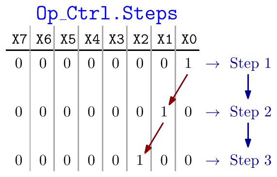
Figure 8.2: Each shift moves the single 1 one place to the left, advancing the step.
Siemens-specific implementation
Shift function: when the
"Shift"."Shift cmd"contact is energised, the bits ofOp_Ctrl.Stepsshift one place to the left (SHLinstruction).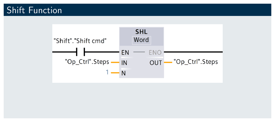
SHL shift instruction Controlling step 2: while step 2 is active, a TON times 1 s;
"Step1_Tim_1s"then goes high,"Shift"."Shift cmd"goes high, and the 1 in the register moves toOp_Ctrl.Steps%X2, the third step.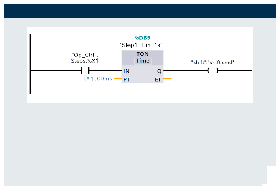
Timer controlling step 2 Switching on the outputs for step 2: while
Op_Ctrl.Steps%X1(step 2) is on, the outputs for tasks B and C (clamping and coolant on) are on, for 1 second.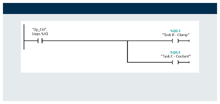
Outputs for step 2
8.3 Logic control of a pick-and-place robot
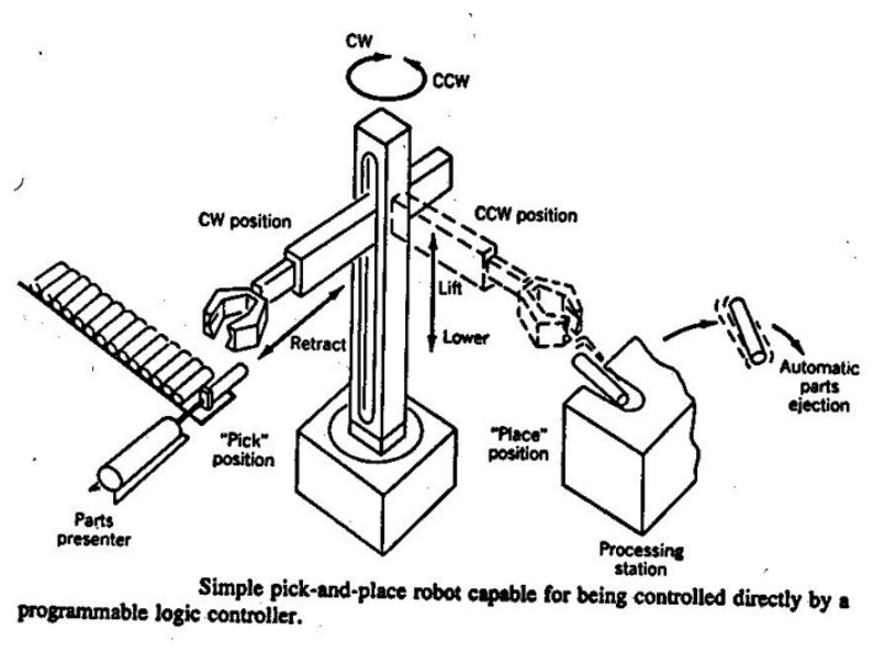
Figure 8.3: A pick-and-place robot that can be driven directly by a PLC.
A 4-axis robot transfers parts from a conveyor to a container. The axes are base rotation, arm raise/lower, arm extend/retract and grip open/close. Each axis holds its position when its output is switched off, so two PLC outputs are needed per axis, one for each direction.
| Output | Action | Input | State (sensor feedback) | |
|---|---|---|---|---|
| 20 | Rotate base counterclockwise | 00 | Base rotated counterclockwise | |
| 21 | Rotate base clockwise | 01 | Base rotated clockwise | |
| 22 | Lift arm | 02 | Arm raised | |
| 23 | Lower arm | 03 | Arm lowered | |
| 24 | Extend arm | 04 | Arm extended | |
| 25 | Retract arm | 05 | Arm retracted | |
| 26 | Close grip | 06 | Grip closed | |
| 27 | Open grip | 07 | Grip open |
Home position (defined by the user, set on start-up): base clockwise (01), arm raised (02), arm retracted (05), grip open (07).
Finding the minimum necessary inputs
To minimise the inputs needed to trigger an output, look at the steps where that output is not allowed.
For step 1 (extend arm), look at steps 1, 5, 6, 11 and 12, i.e. every step where the arm is retracted, and find the smallest combination of inputs unique to step 1:
- 02 is common to all of them, so it’s useless; look for a unique set.
- Choose 01: then only steps 5 and 6 remain, so only 07 is needed as well.
- Choose 05: then steps 6 and 12 remain, needing 07 and 01.
- Choose 07: then steps 11 and 12 remain, so only 01 is needed as well.
So step 1 needs only 01 and 07. For step 5 (retract arm), comparing against steps 1, 2, 3, 4, 7, 8, 9 and 10 shows that 01, 02, 06 is unique to step 5.
| Step | Action | Output | Inputs high before step | Necessary prior inputs |
|---|---|---|---|---|
| 1 | Extend arm | 24 | 01, 02, 05, 07 | 01, 07 |
| 2 | Lower arm | 23 | 01, 02, 04, 07 | 01, 04, 07 |
| 3 | Grip on | 26 | 01, 03, 04, 07 | 01, 03 |
| 4 | Raise arm | 22 | 01, 03, 04, 06 | 01, 06 |
| 5 | Retract arm | 25 | 01, 02, 04, 06 | 01, 02, 06 |
| 6 | Rotate ccw | 20 | 01, 02, 05, 06 | 05, 06 |
| 7 | Extend arm | 24 | 00, 02, 05, 06 | 00, 06 |
| 8 | Lower arm | 23 | 00, 02, 04, 06 | 00, 04, 06 |
| 9 | Grip off | 27 | 00, 03, 04, 06 | 00, 03 |
| 10 | Raise arm | 22 | 00, 03, 04, 07 | 00, 07 |
| 11 | Retract arm | 25 | 00, 02, 04, 07 | 00, 02, 07 |
| 12 | Rotate cw | 21 | 00, 02, 05, 07 | 00, 05, 07 |
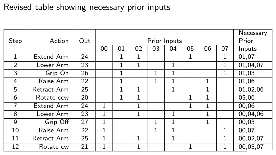
Figure 8.4: The slide’s version of the table.
Building the ladder
For each output, OR together the input conditions of every step that uses it.
Output 24 (extend arm):
( 01 AND 07 OR 00 AND 06 OR 24 ) AND NOT 04 AND 10 ──> (24)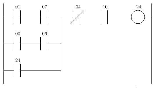
Figure 8.5: Rung for output 24.
- Contacts 01 and 07 come from step 1; contacts 00 and 06 from step 7.
- Contact 24 is the output itself, latching it on until the action completes, when sensor 04 turns on (so NOT 04 opens).
- Contact 10 is a power switch, included in every rung.
Output 26 (close grip):
( 01 AND 03 OR 26 ) AND NOT 06 AND 10 ──> (26)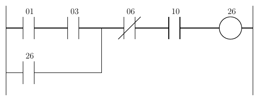
Figure 8.6: Rung for output 26.
8.4 Interlocking vs staged programs
Logic control needs careful analysis to avoid triggering an output at the wrong point in the cycle. The right input conditions must be used to avoid conflicts; this is called interlocking. It is needed because the program runs repeatedly at high speed compared with the mechanical operations, so all rungs effectively execute at once.
Some PLCs allow staged programs: the program only partly executes and waits for an input (such as a signal confirming an operation is complete) before moving on to the next stage. Here the order of the rungs matters.
Stage 1:  (24) Extend arm   ── wait for 04 ──>
Stage 2:  (23) Lower arm    ── wait for 03 ──>
   ...
Stage 12: (21) Rotate cw    ── wait for 01 ──> Jump to Stage 1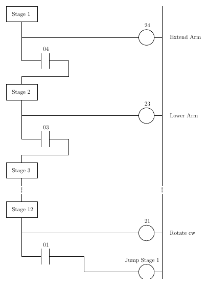
Figure 8.7: Staged program.
- The stages run sequentially because the operations don’t overlap; they could run in parallel if needed.
- Staged programs are much easier to follow and need fewer inputs to trigger outputs, so debugging is much simpler than with interlocked programs. (In IEC 61131-3 this style is formalised as Sequential Function Charts.)
Key points
- Sequencing is open loop, using timers; logic control is closed loop, using sensors.
- A step register with a shift instruction is a neat way to implement a timed sequence.
- For interlocked logic control, find the minimum unique input set for each step, OR the steps per output, latch, and break the latch with the completion sensor.
Interactive applets
Each applet runs in the page; use Open full screen for more room, or open all of this chapter’s applets together.
Applet 8.1 · Multiple activity chart → step matrix builder
Drag bars for tasks A–H on a timeline; the applet draws step boundaries wherever a bar starts or ends and fills in the step/output matrix.
Teaches: How steps are identified. · Open full screen ↗
Applet 8.2 · Shift-register sequencer
Animate the 8-bit Op_Ctrl.Steps register with a 1 shifting left on each timer expiry; lamps for outputs A–H light according to the matrix, and a playback slider scrubs through the cycle.
Teaches: Register-based sequencing on the S7-1200. · Open full screen ↗
Applet 8.3 · Pick-and-place robot simulator
A 2-D or 3-D robot driven by the learner’s ladder program, with sensor inputs 00–07 displayed live. Wrong interlocks cause visible faults (the arm extends while rotating, the grip opens mid-air).
Teaches: Interlocking, latching and the minimum-input analysis. · Open full screen ↗
Applet 8.4 · Minimum unique input finder
Select a step; the applet highlights the conflicting steps, and the learner ticks inputs until the set is unique, with instant feedback.
Teaches: The systematic method behind the “necessary prior inputs” column. · Open full screen ↗
Applet 8.5 · Interlocked vs staged side by side
The same robot cycle is shown as an interlocked ladder and as a staged program, with the active stage highlighted.
Teaches: Readability and debugging benefits of staged programs. · Open full screen ↗