Lecture 9: AC Power
RMS Values
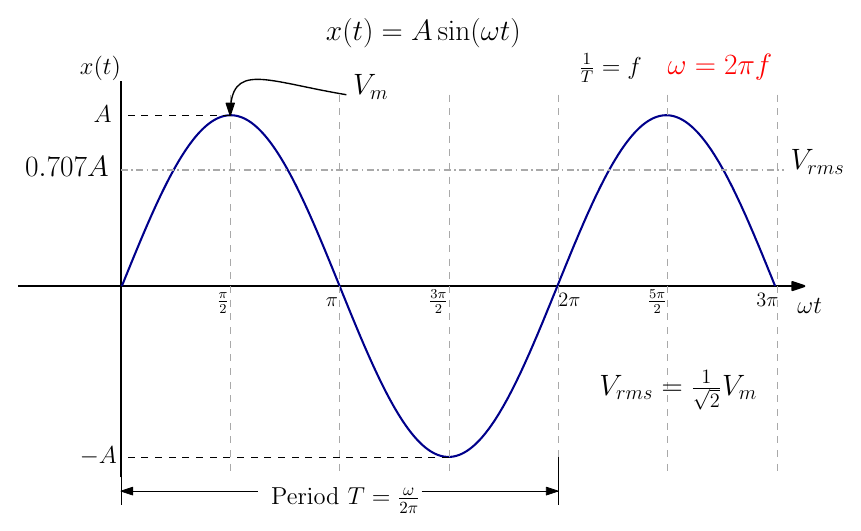
The root mean square (rms) value of a sinusoidal voltage or current can be considered as the effective voltage: the DC value that would deliver the same power. For a sine wave of peak value \(V_m\),
\[ V_{rms} = \frac{1}{\sqrt{2}}\,V_m = 0.707\,V_m \]
Unless stated otherwise, rms values are used for all calculations.
Power in Resistive, Capacitive and Inductive Circuits
Resistive circuit
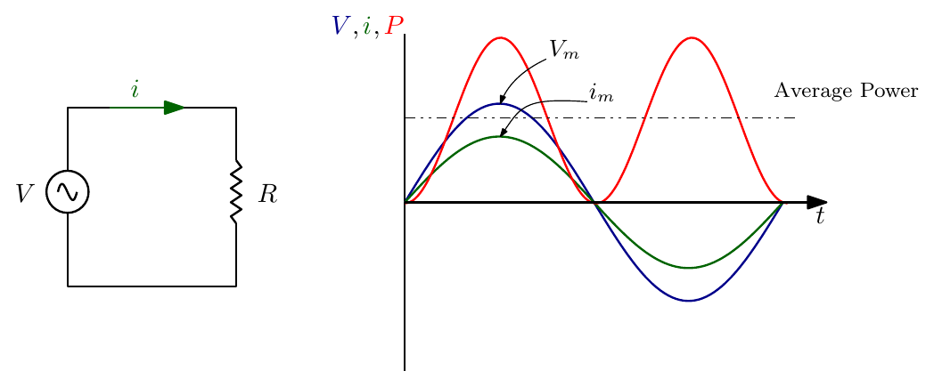
The average power over one period \(T = 2\pi/\omega\) is
\[ P = \frac{\omega}{2\pi}\int_0^{2\pi/\omega} \big(V_m\sin\omega t \cdot i_m\sin\omega t\big)\,dt = V_m i_m\,\frac{\omega}{2\pi}\int_0^{2\pi/\omega} \frac{1 - \cos 2\omega t}{2}\,dt \]
\[ P = V_m i_m \cdot \frac{\omega}{2\pi}\cdot\frac{2\pi}{2\omega} = \frac{V_m\,i_m}{2} = V_{rms}\,i_{rms} \]
- For AC circuits, the power in a resistor is \(V\,i\), where \(V\) and \(i\) are rms values.
- This is consistent with DC, where the power can also be written as \(P = i^2R\).
Capacitive circuit
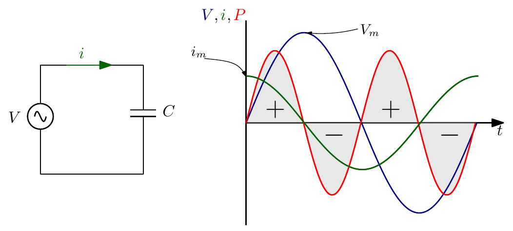
With the current leading the voltage by 90°, the instantaneous power is \(V_m\sin\omega t \cdot i_m\cos\omega t = \tfrac{1}{2}V_m i_m\sin 2\omega t\), so
\[ P = V_m i_m\,\frac{\omega}{2\pi}\int_0^{2\pi/\omega} \frac{\sin 2\omega t}{2}\,dt = V_m i_m\,\frac{\omega}{2\pi}\left[-\frac{\cos 2\omega t}{4\omega}\right]_0^{2\pi/\omega} = 0 \]
- The average power dissipated in a purely capacitive circuit is zero.
- The instantaneous power may be positive or negative (energy flows into the capacitor’s electric field and back out again), but on average no power is consumed.
Inductive circuit
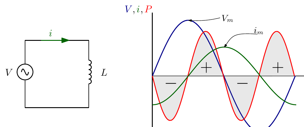
- By the same reasoning, no power is consumed in a purely inductive circuit: energy is stored in the magnetic field and returned each half cycle.
- No circuit is purely resistive, capacitive or inductive in practice.
- Saying that no net power is consumed is another way of saying that no useful (real) power is delivered.
Active and Reactive Power
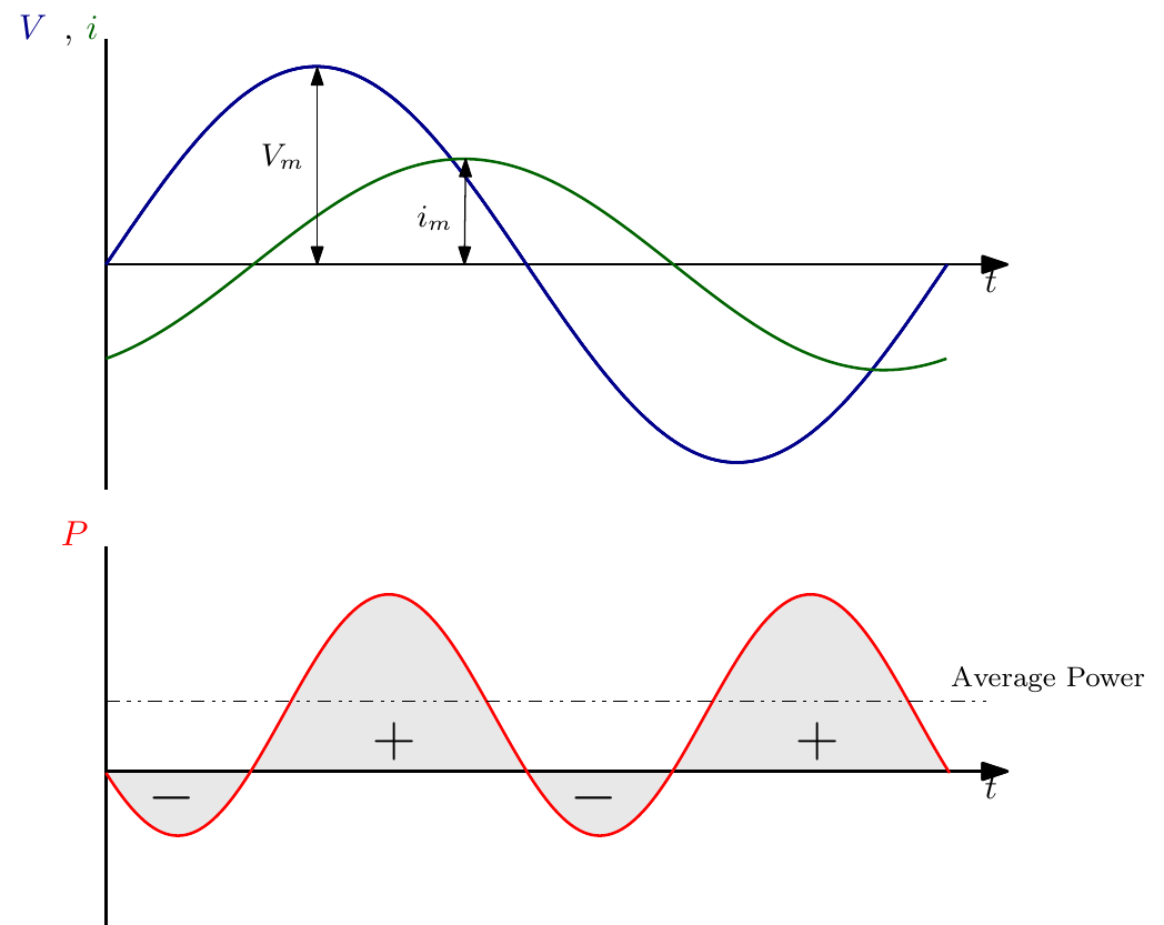
If a circuit contains both resistive and reactive (capacitive or inductive) components:
- The net power available lies somewhere between zero (reactive only) and \(V\,i\) (resistive only).
- Equivalently, the phase angle between voltage and current lies between 90° (reactive) and 0° (resistive).
- As with impedance, where reactive components cause a 90° lead or lag, the reactive components produce what is known as imaginary or reactive power.
- The usable power, from the resistive components, is called active, true or real power.
The Power Triangle
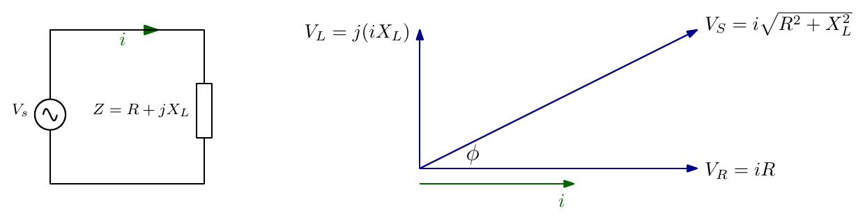
Consider a circuit with a complex impedance. For the purpose of explanation we assume a net inductive reactance (it could equally be net capacitive).
- As before, the voltage phasor diagram is obtained by multiplying each impedance or resistance by the current \(i\).
- Multiplying the voltage phasors by \(i\) again gives the active and reactive powers.
- The active and reactive components form a resultant vector; the figure they make is called the power triangle.
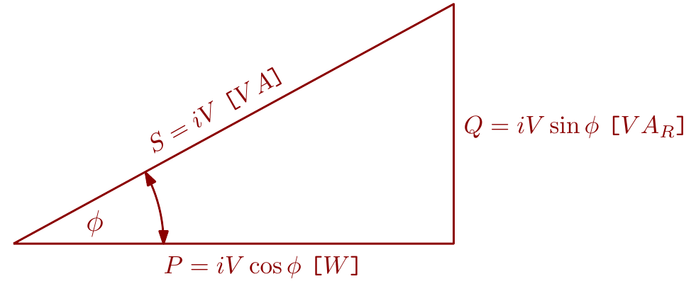
| Quantity | Expression | Units |
|---|---|---|
| Real or active power | \(P = iV\cos\varphi\) | watts, W |
| Imaginary or reactive power | \(Q = iV\sin\varphi\) | volt-amperes reactive, VAR |
| Apparent power | \(S = iV\) | volt-amperes, VA |
\[ S = \sqrt{P^2 + Q^2} \]
Power Factor
In AC, the product of the rms applied voltage and current is \(iV\), the apparent power. The active power is \(P = iV\cos\varphi\), where \(\cos\varphi\) lies between 0 and 1, so \(P\) is less than or equal to \(S = iV\) depending on \(\varphi\).
The ratio of active power to apparent power is called the power factor:
\[ \text{power factor} = \frac{\text{active power } P \text{ (W)}}{\text{apparent power } S \text{ (VA)}} = \cos\varphi = \frac{P}{S} = \frac{P}{iV} \]
From the impedance phasor diagram we can also see that
\[ \cos\varphi = \frac{R}{|Z|} \]
By convention the power factor is lagging when the current lags the supply voltage (an inductive load) and leading when the current leads the supply voltage (a capacitive load): the supply voltage is the reference.
Other useful forms of the powers:
\[ P = iV\cos\varphi = i^2|Z|\cos\varphi = i^2R, \qquad Q = iV\sin\varphi = i^2|Z|\sin\varphi = i^2X, \qquad S = iV = i^2|Z| \]
Worked Example
A resistance of 10 Ω is connected in series with an inductive reactance of 5 Ω across a 240 V, 50 Hz power supply. Determine (a) the impedance of the load, (b) the current drawn from the supply, (c) the power factor, (d) the real power, (e) the reactive power, (f) the apparent power, and (g) the complex power.
(a) Impedance
\[ Z = R + jX_L = (10 + j5)\ \Omega, \qquad |Z| = \sqrt{10^2 + 5^2} = 11.18\ \Omega, \qquad \varphi = \tan^{-1}\!\left(\frac{5}{10}\right) = 26.56^\circ \]
In polar form, \(Z = 11.18\angle 26.56^\circ\ \Omega\).
(b) Current. Taking the 240 V rms supply as the reference phasor (phase angle zero):
\[ i = \frac{V}{Z} = \frac{240 + j0}{10 + j5} = \frac{240\angle 0^\circ}{11.18\angle 26.56^\circ} = 21.47\angle -26.56^\circ\ \text{A} \]
(c) Power factor. The current lags the voltage by 26.56°:
\[ \text{pf} = \cos 26.56^\circ = 0.894 \text{ lagging} \]
(d) Real power
\[ P = iV\cos\varphi = 21.47 \times 240 \times 0.894 = 4.61\ \text{kW} \qquad \text{or} \qquad P = i^2R = 21.47^2 \times 10 = 4.61\ \text{kW} \]
(e) Reactive power
\[ Q = iV\sin\varphi = 21.47 \times 240 \times \sin 26.56^\circ = 2.30\ \text{kVAR} \qquad \text{or} \qquad Q = i^2X_L = 21.47^2 \times 5 = 2.30\ \text{kVAR} \]
(f) Apparent power
\[ S = \sqrt{P^2 + Q^2} = \sqrt{4.61^2 + 2.30^2} = 5.15\ \text{kVA} \]
(g) Complex power. The complex power is the voltage times the complex conjugate of the current:
\[ \mathbf{S} = V\,i^{*} = (240\angle 0^\circ)(21.47\angle +26.56^\circ) = 5153\angle 26.56^\circ\ \text{VA} = (4.61 + j2.30)\ \text{kVA} \]
Its real part is \(P\) and its imaginary part is \(Q\), positive for an inductive (lagging) load.
Note: the slide multiplies \(V\) by \(i\) directly and writes \(5153\angle -26.56^\circ\). The magnitude is the same, but using the conjugate \(i^{*}\) is the standard definition: it gives the angle \(+26.56^\circ\), so that \(Q\) comes out positive for an inductive load, matching part (e).
Power Factor: Practical Implications
If an AC generator is rated to give 2000 A at 400 V, these are the highest current and voltage the machine can deliver without its temperature exceeding a safe value. Its rating is
\[ 400 \times 2000 = 800\ \text{kVA} \]
The phase difference between the voltage and the current depends on the nature of the load, not on the generator.
| Load power factor 1 | Load power factor 0.5 |
|---|---|
| Generator developing 800 kVA | Generator developing 800 kVA |
| Active power out: 800 kW | Active power out: 400 kW |
The higher the power factor of the load, the greater the active power a given generator can deliver. Supply authorities do all they can to improve the power factor of their loads, through capacitors, special machines, or tariffs that encourage consumers to do so.
Power Factor Correction
The power factor of a load can be improved (increased) by adding equipment that absorbs VAR in the opposite sense to the load. If the load is inductive (lagging power factor), the correcting equipment should present a capacitive load. The cost of the correction equipment has to be balanced against the resulting savings in electricity charges.
Example. Calculate the size of the capacitor needed, for the load in the worked example above, to (a) correct the power factor to unity, and (b) correct it to 0.96 lagging.
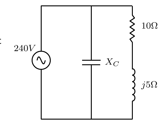
(a) Unity power factor. The capacitor must supply 2.3 kVAR to cancel the load’s 2.3 kVAR of inductive reactive power. The capacitor’s current is \(i = V/X_C\) and \(Q = i^2X_C\), so
\[ Q = \frac{V^2}{X_C} \;\Rightarrow\; X_C = \frac{V^2}{Q} = \frac{240^2}{2300} = 25\ \Omega \]
\[ C = \frac{1}{2\pi f X_C} = \frac{1}{2\pi \times 50 \times 25} = 127\ \mu\text{F} \]
(b) 0.96 lagging. The new phase angle is \(\cos^{-1}0.96 = 16.3^\circ\). The real power is unchanged at 4.61 kW, so from the power triangle
\[ Q_{new} = P\tan 16.3^\circ = 4.61 \times 10^3 \times \tan 16.3^\circ = 1.35\ \text{kVAR} \]
The capacitor must supply \(2.3 - 1.35 = 0.95\) kVAR:
\[ X_C = \frac{240^2}{950} = 61\ \Omega, \qquad C = \frac{1}{2\pi \times 50 \times 61} = 52\ \mu\text{F} \]
Correcting only to 0.96 needs well under half the capacitance of full correction, which is why loads are rarely corrected all the way to unity.
Further viewing
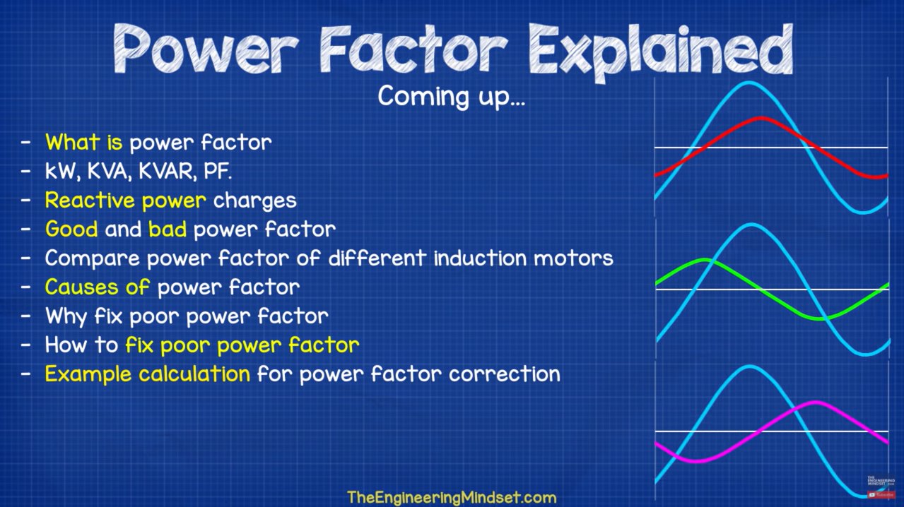
Engineering Mindset video: “Power Factor Explained” (what power factor is; kW, kVA, kVAR; reactive power charges; causes of poor power factor; and power factor correction).
Interactive Elements
Each element below runs in the page; use Open full screen for more room.
Instantaneous power explorer
Choose a load phase angle from 0° (resistive) to ±90° (purely reactive) and watch \(v(t)\), \(i(t)\) and \(p(t) = v\,i\), with the positive and negative lobes shaded and the average power drawn. At 90° the lobes cancel exactly, at 0° the power never goes negative.
Power triangle builder
Sliders for \(R\), \(X\) (inductive or capacitive) and the supply voltage, drawing the impedance triangle and the power triangle side by side with \(P\), \(Q\), \(S\) and the power factor (leading or lagging) worked out. The worked example’s values reproduce the lecture’s answers.
Power factor correction
Start from a lagging load, add a parallel capacitor with a slider, and watch \(Q\) shrink, the power factor rise and the supply current fall, with the capacitance for a target power factor calculated. Pushing past unity shows the load becoming leading.
Generator capacity
An 800 kVA generator feeding loads of different power factor, showing how much useful kW it can deliver at each.
Knowledge Check
Q1. A sinusoidal voltage has a peak value of 325 V. What is its rms value?
Answer
\(V_{rms} = V_m/\sqrt{2} = 325 \times 0.707 \approx 230\) V. (This is the European mains supply.)
Q2. What is the average power consumed by a pure capacitor or a pure inductor connected to an AC supply, and why?
Answer
Zero. The voltage and current are 90° apart, so the instantaneous power is positive for half the time (energy stored in the electric or magnetic field) and negative for the other half (energy returned to the supply). The two cancel over a cycle.
Q3. Match each quantity to its unit: real power, reactive power, apparent power — W, VA, VAR.
Answer
Real (active) power \(P\): W. Reactive power \(Q\): VAR. Apparent power \(S\): VA.
Q4. Define power factor in three equivalent ways.
Answer
\(\text{pf} = \dfrac{P}{S} = \cos\varphi = \dfrac{R}{|Z|}\): the ratio of real to apparent power, the cosine of the angle between voltage and current, or the ratio of resistance to impedance magnitude.
Q5. A load draws 10 A from a 230 V supply at a power factor of 0.8 lagging. Find \(S\), \(P\) and \(Q\).
Answer
\(S = iV = 10 \times 230 = 2.3\) kVA; \(P = S\cos\varphi = 2.3 \times 0.8 = 1.84\) kW; \(\sin\varphi = 0.6\), so \(Q = S\sin\varphi = 1.38\) kVAR.
Q6. Is the power factor of a motor (an inductive load) leading or lagging? What would you connect to correct it?
Answer
Lagging, because the current lags the voltage in an inductive load. It is corrected by connecting capacitors in parallel, which supply reactive power in the opposite sense.
Q7. Why do supply authorities want consumers to have a high power factor?
Answer
Generators, cables and transformers are rated by current and voltage (kVA), not by kW. A low power factor means more current, and so more rated capacity and more losses, for the same useful power. For example an 800 kVA generator delivers only 400 kW to a load at power factor 0.5, but 800 kW at power factor 1.
Q8. In the worked example, why was the power factor corrected to 0.96 rather than to unity?
Answer
Correcting to 0.96 needed only 52 µF instead of 127 µF. The cost of correction equipment has to be balanced against the savings, and the last few percent towards unity need disproportionately more capacitance.
Q9. A 20 Ω resistor and an inductor of reactance 15 Ω are in series across 100 V. Find the current, the power factor and the real power.
Answer
\(|Z| = \sqrt{20^2 + 15^2} = 25\ \Omega\), \(i = 100/25 = 4\) A, \(\text{pf} = R/|Z| = 20/25 = 0.8\) lagging, and \(P = i^2R = 4^2 \times 20 = 320\) W (check: \(iV\cos\varphi = 4 \times 100 \times 0.8 = 320\) W).
Q10. For a capacitor that must supply \(Q\) VAR at a supply voltage \(V\) and frequency \(f\), derive the required capacitance.
Answer
\(Q = V^2/X_C\) gives \(X_C = V^2/Q\), and \(X_C = 1/(2\pi f C)\), so \(C = \dfrac{Q}{2\pi f V^2}\).