Logic Diagrams and Response Diagrams
Chapter 4 · Part I: Logic Control Fundamentals · Sources: Lectures 3, 4 and 5
4.1 Why logic diagrams?
Most automated processes use timers, memories, counters and delays, which can’t be expressed in Boolean algebra. Graphical methods are used instead.
Basic gates and the panel switch with lock
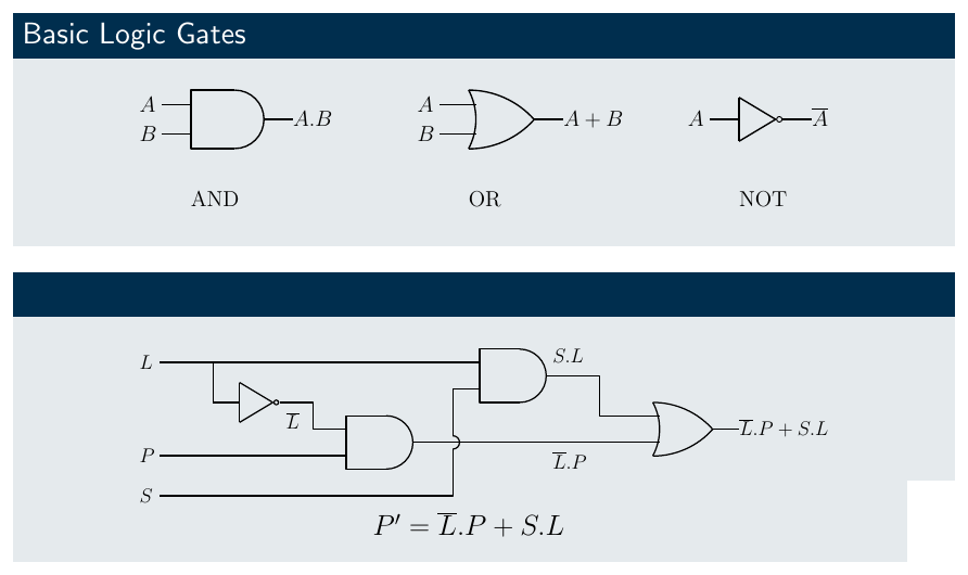
Figure 4.1: AND, OR and NOT gates (top); panel switch with lock (bottom).
\(\overline{L}\) AND \(P\) gives \(\overline{L}.P\); \(S\) AND \(L\) gives \(S.L\); these are ORed to give
\[P' = \overline{L}.P + S.L\]
Cascaded gates and additional operators
AND and OR gates can be cascaded or given multiple inputs; e.g. two cascaded 2-input ANDs are the same as one 3-input AND giving \(A.B.C\). Other operators are added as a titled box, e.g. a Delay 5 s block.
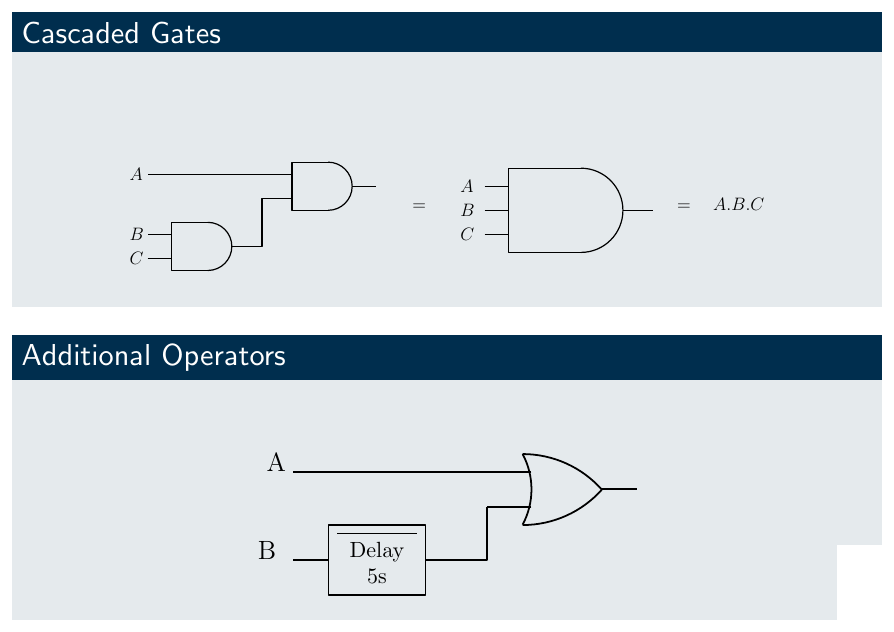
Figure 4.2: Cascaded gates and a delay operator.
Memory function
The panel switch with lock can be drawn as a memory block: the output follows the set command (S) while the enable input (L) is high. When enable is low, the output stays unchanged.

Figure 4.3: The switch with lock as a memory function.
Multiple outputs
A network can have several outputs, e.g. \(X = A.B\), \(Y = A + B\) and \(Z = \overline{A + B}\) (the OR output through a NOT gate).
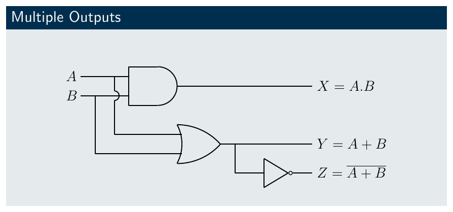
Figure 4.4: Multiple outputs from one network.
4.2 Response diagrams
In response diagrams, the states of the inputs and outputs are plotted against time and synchronised.
- The inputs are chosen by the designer and are arbitrary, but should cover all possible situations.
- The outputs then follow from the logic of the system.
In the conveyor example (Chapter 5), a heavy item is detected at 2 s and at 9 s, and the trap-door output goes on for 4 s after each detection:
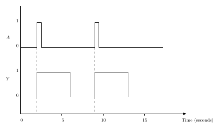
Figure 4.5: Conveyor reject response diagram.
AND gate response
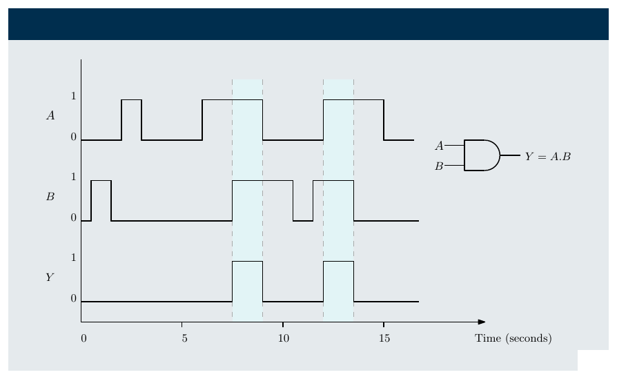
Figure 4.6: \(Y = A.B\) is high only where A and B overlap (shaded).
Memory (set/reset) responses
A memory block has a set input A and a reset input B. When only A is high, the output Y switches on and stays on; when only B is high, Y switches off and stays off. The three types differ in what happens when A and B are high at the same time:
| Type | When A and B are both high |
|---|---|
| Off-dominant (reset-dominant) | Y = 0: reset wins |
| On-dominant (set-dominant) | Y = 1: set wins |
| Static-dominant | Y keeps the state it already had: whichever signal arrived first wins, and the later one has no effect until the first is released |
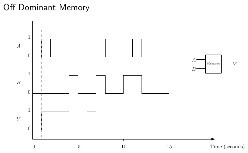
Figure 4.7: Off-dominant memory. At 7–8 s and 11–12 s both inputs are high and Y is off.
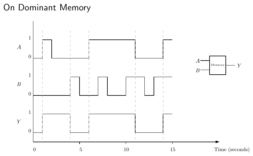
Figure 4.8: On-dominant memory. At 7–8 s and 10–11 s both inputs are high and Y stays on.
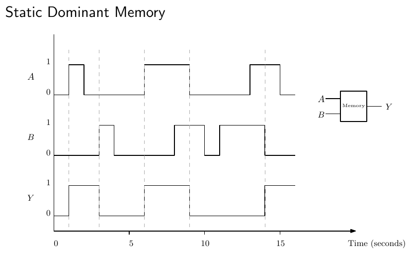
Figure 4.9: Static-dominant memory. At 8–9 s B rises while Y is already on, so Y stays on until A falls; at 13–14 s A rises while Y is off, so Y stays off until B falls.
The interpretation of the three memory types is drawn from the slide waveforms (the slides themselves give only the diagrams).
Off-dominant behaviour is the safe default where the reset is a Stop function, which is why the latch in Chapter 2 gave Stop precedence.
4.3 From logic to response and back
The design workflow used in the worked examples (Chapter 6) is:
- List the inputs and outputs (with respect to the controller).
- Draw a response diagram covering every scenario.
- Derive the logic network by working back from each output.
- Translate the logic network into ladder logic.
Key points
- Logic diagrams can include non-Boolean blocks such as timers, delays and memories.
- Response diagrams verify time-dependent behaviour; choose input scenarios that exercise every case.
- Memory blocks differ in dominance when set and reset are both active.
Interactive applets
Each applet runs in the page; use Open full screen for more room, or open all of this chapter’s applets together.
Applet 4.1 · Logic diagram simulator
Drag gates, timers (TON/TOF) and memory blocks onto a canvas, wire them, and toggle inputs; wires light up when high.
Teaches: Building networks with time-dependent blocks. · Open full screen ↗
Applet 4.2 · Response diagram plotter
Paint input waveforms on a time grid (click and drag to set high/low). The applet computes and plots the output for the selected network (AND, OR, memory, TON).
Teaches: Reading and constructing response diagrams. · Open full screen ↗
Applet 4.3 · Memory dominance explorer
Use the same A/B waveforms with a selector for off-, on- or static-dominant memory; regions where A and B overlap are highlighted, with the differing output.
Teaches: The one situation where the three memory types differ. · Open full screen ↗
Applet 4.4 · Predict-then-reveal quiz
Given input waveforms and a network, the learner sketches the output, then the applet overlays the correct answer and scores the match.
Teaches: Active practice for exam-style response diagram questions. · Open full screen ↗