Finished circuit and Arduino code
This presentation builds the final design-project circuit in six steps. It is the same system as Part 8, drawn with more wiring labels, and with a slightly different version of the code.
Step 1 — power and signals from Arduino to relay
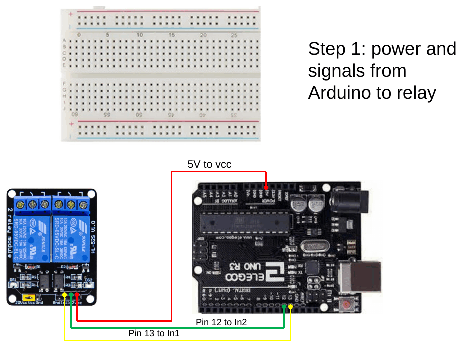
| From (Arduino) | To (relay module) |
|---|---|
| 5 V | VCC |
| GND | GND |
| Pin 13 | IN1 — battery relay |
| Pin 12 | IN2 — RES relay |
Step 2 — relay control of the external power source
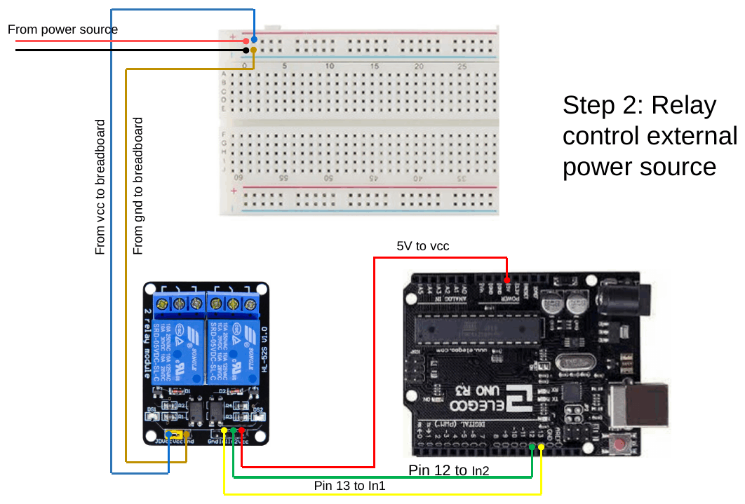
- From VCC to breadboard and from GND to breadboard — run the supply and ground onto the breadboard rails so the rest of the circuit can share them.
- From power source — the external supply rail into the breadboard; this is where the switched power will be distributed to the load.
Step 3 — RES power in through the relay
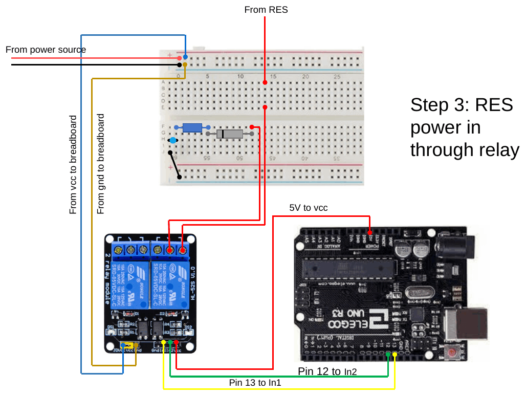
- From RES (+ve) → COM of the RES relay.
- Relay output (NO) → breadboard → load. The load in the prototype is an LED with a series resistor (representing the pump).
Step 4 — don’t forget to ground
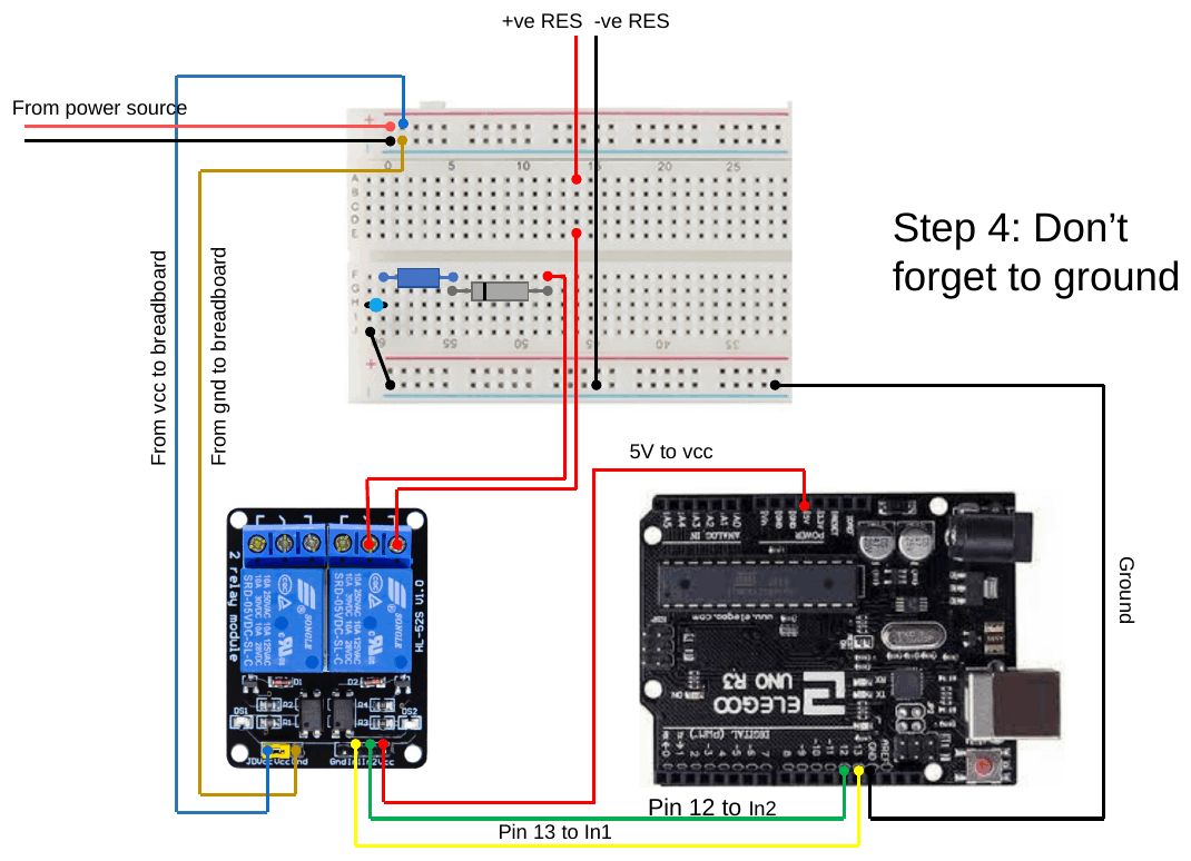
- −ve RES → breadboard ground rail.
- Arduino GND → the same ground rail (long black wire labelled Ground).
Every part of the system must share one ground — otherwise the Arduino cannot measure the RES voltage and the load circuit is not complete.
Step 5 — add battery power
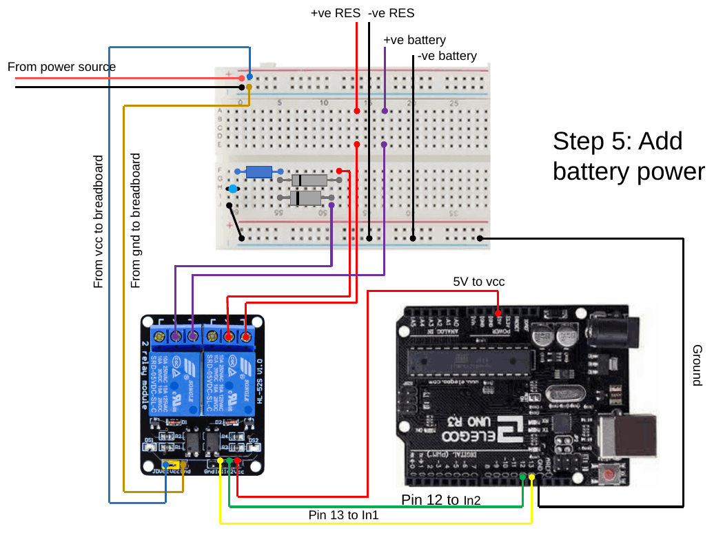
- +ve battery → COM of the battery relay; its NO output joins the load supply.
- −ve battery → ground rail.
Step 6 — add the monitoring system
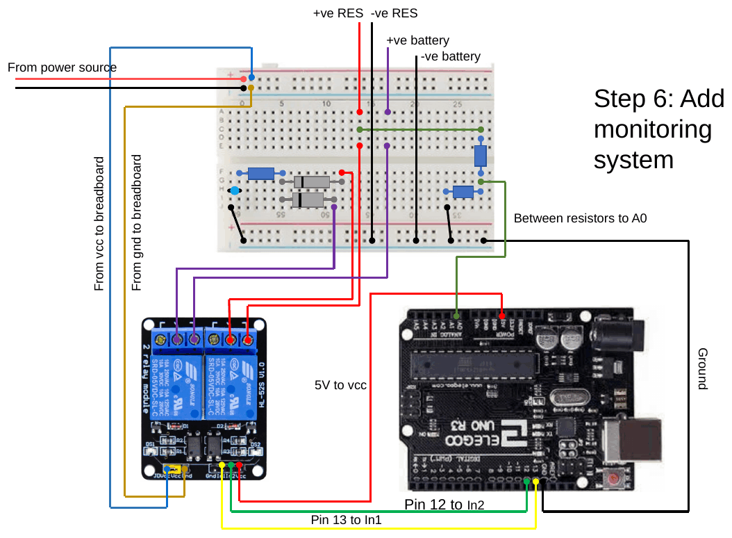
- Two resistors in series across the RES form a voltage divider.
- Between the resistors → A0.
- Choose the resistors so the RES’s maximum voltage gives no more than 5 V at A0 (\(R_1 = (V_{max}/5 - 1)\,R_2\) — see Part 5).
Complete wiring summary
| Connection | From | To |
|---|---|---|
| Relay power | Arduino 5 V | Relay VCC |
| Relay ground | Arduino GND | Relay GND |
| Battery relay control | Arduino pin 13 | IN1 |
| RES relay control | Arduino pin 12 | IN2 |
| RES supply | RES +ve | COM, RES relay |
| Battery supply | Battery +ve | COM, battery relay |
| Load supply | NO of both relays | Load (+) |
| Common ground | RES −ve, battery −ve, Arduino GND, load (−) | Breadboard ground rail |
| Monitoring | RES +ve → R₁ → (A0) → R₂ → ground | Arduino A0 |
Arduino code (as given in the presentation)
int R1pin = 13;   // Battery supply
int R2pin = 12;   // Renewable energy supply
float Vwind = A0;
float Vread;
float Vin = 3.5;
int dt2 = 100;

void setup() {
  // put your setup code here, to run once:
  Serial.begin(9600);
  pinMode(R1pin, OUTPUT);
  pinMode(R2pin, OUTPUT);
  pinMode(Vwind, INPUT);
  // This just sets my system up to take power from the RES system
  digitalWrite(R2pin, LOW);
  digitalWrite(R1pin, HIGH);
}

void loop() {
  // put your main code here, to run repeatedly:
  if (Vin <= 4.8) {
    digitalWrite(R2pin, HIGH);
    digitalWrite(R1pin, LOW);
    Vread = analogRead(Vwind);
    Vin = (5. / 1023.) * Vread;
    Serial.println(Vin);
    // delay(dt2);  // I have the delay turned off because I want my system to respond instantly
  }
  if (Vin > 4.8) {
    digitalWrite(R2pin, LOW);
    digitalWrite(R1pin, HIGH);
    Vread = analogRead(Vwind);
    Vin = (5. / 1023.) * Vread;
    Serial.println(Vin);
    // delay(dt2);
  }
}
Run it: the presentation’s code in the code runner — watch both relays switch on together for a moment at start-up, and the made-up starting value of Vin. · Open full screen ↗
(The closing braces of loop() are cut off at the bottom of the slide; they are added above.)
How it works
- The relay module is active-LOW:
LOWconnects a source,HIGHdisconnects it.setup()therefore starts on the RES (R2pinLOW,R1pinHIGH). Vinholds the last measured A0 voltage. At or below 4.8 V → use the battery (R1pinLOW). Above 4.8 V → use the RES (R2pinLOW).- The delay is commented out so the system responds as quickly as possible.
Points to note
- The relays switch before the new reading is taken. Each
ifblock acts on the previous value ofVin, then reads a new one. It works becauseloop()runs thousands of times per second, but reading first is clearer. Vin = 3.5at start-up means the first pass switches to the battery even thoughsetup()selected the RES.float Vwind = A0;— pin numbers should beint.- 4.8 V is close to the 5 V maximum. With the divider designed so the RES maximum gives 5 V, the system uses the RES only when it is within ~4 % of its peak. Compare the 2.5 V threshold in Part 8. Choose the threshold from the minimum RES voltage your load needs, scaled through the divider.
Updated version
The same behaviour as the presentation’s code, written in the style used throughout these notes:
/*
 * Finished circuit: run the load from the renewable energy source (RES)
 * while its voltage is high enough, and switch to the battery when it drops.
 * Hardware: divider mid-point -> A0; D12 -> IN2 (RES relay);
 *           D13 -> IN1 (battery relay); 5 V -> VCC; all grounds joined.
 */

const uint8_t kResPin     = A0;       // divider mid-point ("between resistors to A0")
const uint8_t kResRelay   = 12;       // IN2: connects the RES to the load
const uint8_t kBatRelay   = 13;       // IN1: connects the battery to the load
const float   kThresholdV = 4.8;      // at or below this (at A0), use the battery
const float   kAdcVref    = 5.0;      // analogRead reference voltage (V)
const float   kAdcMax     = 1023.0;   // largest analogRead value
const uint8_t kRelayOn    = LOW;      // the relay module is active-LOW
const uint8_t kRelayOff   = HIGH;

// Read an analogue pin and return the voltage on it (0 to 5 V).
float readVolts(uint8_t pin) {
  return analogRead(pin) * (kAdcVref / kAdcMax);
}

// Power the load from the RES. The battery is disconnected first.
void useRes() {
  digitalWrite(kBatRelay, kRelayOff);
  digitalWrite(kResRelay, kRelayOn);
}

// Power the load from the battery. The RES is disconnected first.
void useBattery() {
  digitalWrite(kResRelay, kRelayOff);
  digitalWrite(kBatRelay, kRelayOn);
}

void setup() {
  Serial.begin(9600);
  digitalWrite(kResRelay, kRelayOff);    // both relays off until we decide
  digitalWrite(kBatRelay, kRelayOff);
  pinMode(kResRelay, OUTPUT);
  pinMode(kBatRelay, OUTPUT);
  useRes();                              // start on the renewable source
}

void loop() {
  float vIn = readVolts(kResPin);        // 1. read the RES voltage first ...
  Serial.println(vIn);

  if (vIn <= kThresholdV) {              // 2. ... then decide
    useBattery();
  } else {
    useRes();
  }
  // No delay(): the system responds as quickly as possible, as in the original.
}
Run it: the updated version in the code runner — drag the A0 voltage either side of 4.8 V. · Open full screen ↗
Explainer: what changed from the presentation’s code, and why
| Presentation’s code | Updated version | Why |
|---|---|---|
| Switches the relays, then reads the new voltage | Reads first, then switches | Each decision is based on the latest reading |
float Vin = 3.5; at start-up |
No made-up starting value | The first decision uses a real measurement, so the system doesn’t briefly switch to the battery at power-up |
float Vwind = A0; |
const uint8_t kResPin = A0; |
Pin numbers are whole numbers that never change |
Two separate if blocks |
One if ... else |
Exactly one branch runs on every pass |
digitalWrite(..., LOW) meaning “on” |
useRes() / useBattery() with kRelayOn / kRelayOff |
The active-LOW logic is written down once; loop() reads like the task |
| Old source and new source switched in either order | Old source off before new source on | The RES and battery are never connected together, even for an instant |
The threshold is still 4.8 V at A0, as in the presentation. Part 8 uses 2.5 V and shows how to add hysteresis (two thresholds) so the relays don’t chatter when the voltage hovers near the switching point.
Try it: RES battery-backup simulator — set the threshold slider to 4.8 V and compare with 2.5 V. · Open full screen ↗