Lecture 14: Equivalent Circuit
The Induction Motor Equivalent Circuit
In Lecture 13 we found that the frequency of the rotor e.m.f., also called the slip frequency, is the slip times the stator frequency:
\[ f_r = s\,f \quad \Rightarrow \quad \omega_{slip} = s\,\omega \]
This helps us develop an equivalent circuit for the induction motor. An input voltage drives the stator coils, which in turn induce a voltage in the rotor: much like the transformer of Lecture 10. Care is needed on the rotor side to account for slip, but we have an expression for the slip frequency.*
* Treating the motor as a transformer is a slight over-simplification of the conditions for the transformer model to be valid, but the model in this lecture is a valid one.
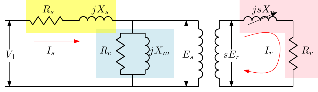
- \(R_s + jX_s\) represent the stator windings.
- \(R_c\) represents the iron core losses (hysteresis and eddy currents).
- \(jX_m\) is the magnetising reactance across the air gap.
- \(R_r + jsX_r\) represent the rotor windings.
- \(E_s\) and \(sE_r\) are the e.m.f.s in the stator and rotor.
The Rotor Side
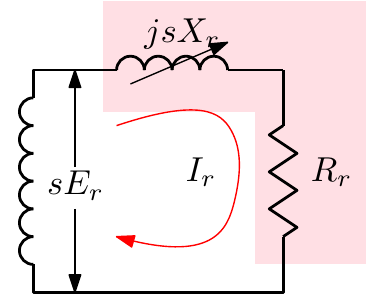
The induced rotor e.m.f. depends on the rotor frequency, which depends on the slip \(s\), so the rotor current is
\[ I_r = \frac{sE_r}{Z_r} = \frac{sE_r}{R_r + jsX_r} \]
Dividing the top and bottom by \(s\):
\[ I_r = \frac{E_r}{\dfrac{R_r}{s} + jX_r} \]
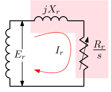
The rotor can therefore be redrawn with the standstill e.m.f. \(E_r\) and reactance \(X_r\), and a slip-dependent resistance \(R_r/s\).
Simplifying the Model
Further simplifications:
- Refer the rotor impedances to the stator side, as with the transformer: \(X_r\) becomes \(X_r'\) and \(\dfrac{R_r}{s}\) becomes \(\dfrac{R_r'}{s}\).
- \(R_c\) is often negligible and can be removed.
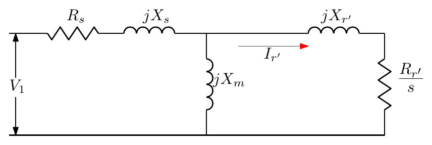
To simplify the analysis further, the magnetising branch can be moved to the supply side:
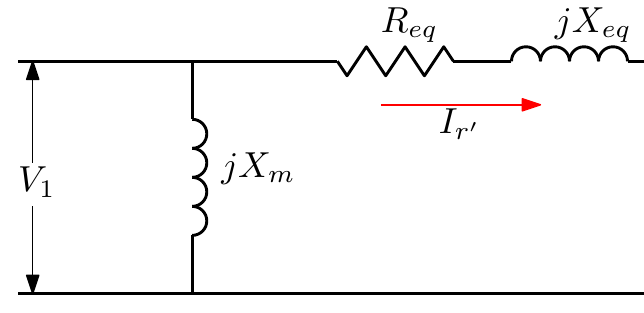
\[ R_{eq} = R_s + \frac{R_r'}{s}, \qquad X_{eq} = X_s + X_r' \]
These simplifications are exactly that: simplifications. They make the engineer’s calculations easier, but each one moves the answer further from the real-world value. As an engineer, you must judge how simple to make the model.
“Everything should be made as simple as possible, but no simpler.” — attributed to Albert Einstein
Power and Torque
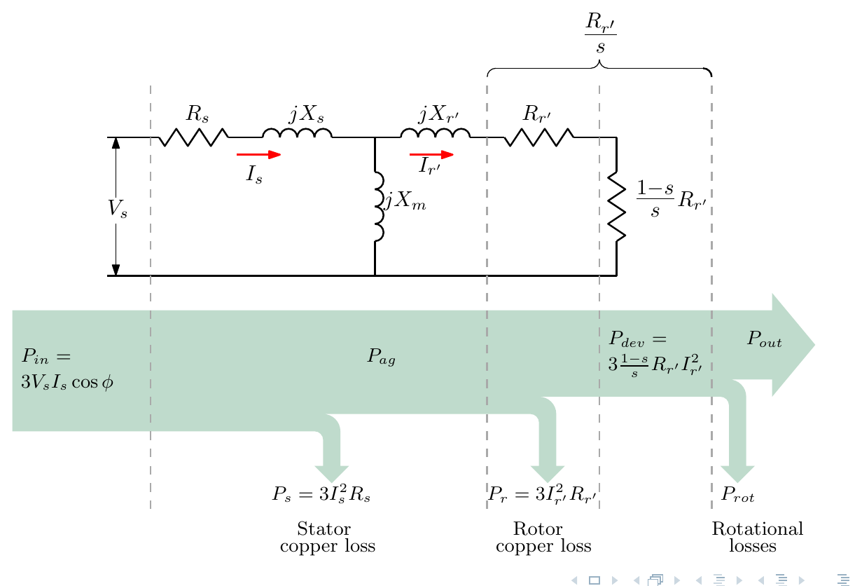
The key step is to split the referred rotor resistance \(R_r'/s\) into two parts:
\[ \frac{R_r'}{s} = R_r' + \frac{1 - s}{s}\,R_r' \]
- The power delivered to \(\dfrac{1-s}{s}R_r'\) is the mechanical power developed.
- The power in \(R_r'\) is the rotor copper loss.
For three phases:
\[ P_{dev} = 3\,I_r'^2\,\frac{1 - s}{s}\,R_r', \qquad P_r = 3\,I_r'^2\,R_r' \]
Power flow
\[ P_{in} = 3\,V_s I_s\cos\varphi \;\longrightarrow\; P_{ag} = P_{in} - P_s \;\longrightarrow\; P_{dev} = P_{ag} - P_r \;\longrightarrow\; P_{out} = P_{dev} - P_{rot} \]
where \(P_s = 3I_s^2R_s\) is the stator copper loss and \(P_{rot}\) the rotational losses: friction and windage, into which the core loss (from \(R_c\) in the earlier model) can also be folded. The efficiency is
\[ \eta = \frac{P_{out}}{P_{in}} \times 100\% \]
Air-gap power and torque
The air-gap power is the rotor copper loss plus the developed power:
\[ P_{ag} = P_r + P_{dev} = 3I_r'^2R_r' + 3I_r'^2\,\frac{1 - s}{s}R_r' = 3\,I_r'^2\,\frac{R_r'}{s} \]
so
\[ P_r = s\,P_{ag}, \qquad P_{dev} = (1 - s)\,P_{ag} \]
The developed torque is
\[ T_{dev} = \frac{P_{dev}}{\omega_r} = \frac{(1 - s)\,P_{ag}}{\omega_r} \]
and since the rotor speed is \(\omega_r = (1 - s)\,\omega_s\),
\[ T_{dev} = \frac{P_{ag}}{\omega_s} \]
The torque can be found from the air-gap power and the synchronous speed. Speeds must be in rad/s: \(\omega = \dfrac{\pi}{30}N\) for \(N\) in rpm.
Worked Example 1
The per-phase parameters of the equivalent circuit for a 400 V, 25 kW, 50 Hz, three-phase, star-connected, four-pole, 1445 rpm induction motor are \(R_s = 0.4\ \Omega\), \(X_s = 0.75\ \Omega\), \(X_m = 22\ \Omega\), \(R_r' = 0.2\ \Omega\), \(X_r' = 0.2\ \Omega\). The mechanical losses are 500 W and the iron losses 250 W. At full load and rated speed, determine (a) the synchronous speed, (b) the slip, (c) the input current and power factor, (d) the input power, (e) the useful mechanical output power, (f) the output torque, and (g) the efficiency.
Corrections to the slides. The solution below follows the lecture’s method, with three errors fixed: (i) \(Z_r + Z_s = 5.8 + j0.95\ \Omega\), not \(5.8 + j0.4\ \Omega\) (the slide’s polar form, \(5.88\angle 9.3^\circ\), is correct, but the \(j0.4\) was carried into the next step); (ii) the stator and rotor copper losses on the slide are half their correct values; and (iii) the torque must be calculated with speeds in rad/s, not rpm. The slide’s 16.4 N·m is about 9.5 times too small.
(a) Synchronous speed. Four poles is two pole pairs:
\[ N_s = \frac{60f}{p} = \frac{60 \times 50}{2} = 1500\ \text{rpm} \]
(b) Slip
\[ s = \frac{N_s - N_r}{N_s} = \frac{1500 - 1445}{1500} = 0.037 \]
(c) Input current and power factor. Using the approximate equivalent circuit, with \(jX_m\) across the supply. The machine is star-connected, so the phase voltage is \(400/\sqrt{3} = 230.9\) V.
\[ Z_r = \frac{R_r'}{s} + jX_r' = \frac{0.2}{0.037} + j0.2 = 5.41 + j0.2\ \Omega, \qquad Z_s = 0.4 + j0.75\ \Omega \]
\[ Z_r + Z_s = 5.81 + j0.95\ \Omega = 5.88\angle 9.3^\circ\ \Omega, \qquad Z_m = j22\ \Omega = 22\angle 90^\circ\ \Omega \]
\[ Z_{tot} = Z_m \,\|\, (Z_r + Z_s) = \frac{Z_m(Z_r + Z_s)}{Z_m + (Z_r + Z_s)} = \frac{(22\angle 90^\circ)(5.88\angle 9.3^\circ)}{5.81 + j22.95} = \frac{129.4\angle 99.3^\circ}{23.67\angle 75.8^\circ} = 5.47\angle 23.5^\circ\ \Omega \]
\[ I = \frac{V}{Z_{tot}} = \frac{230.9\angle 0^\circ}{5.47\angle 23.5^\circ} = 42.2\angle -23.5^\circ\ \text{A} \]
The power factor is \(\cos 23.5^\circ = 0.917\) lagging.
(d) Input power
\[ P_{in} = \sqrt{3}\,V_lI_l\cos\varphi = \sqrt{3} \times 400 \times 42.2 \times 0.917 = 26.84\ \text{kW} \]
(e) Useful mechanical output power. In the approximate circuit, the stator and rotor resistances carry the series-branch current
\[ I_r' = \frac{V}{Z_r + Z_s} = \frac{230.9}{5.88} = 39.3\ \text{A} \]
(the rest of the 42.2 A input current is the magnetising current in \(jX_m\), which carries no real power).
- Stator copper loss: \(3I_r'^2R_s = 3 \times 39.3^2 \times 0.4 = 1849\) W
- Air-gap power: \(P_{ag} = 3I_r'^2\dfrac{R_r'}{s} = 24\,992\) W (check: \(26\,842 - 1849 = 24\,993\) W)
- Rotor copper loss: \(sP_{ag} = 925\) W
- Developed power: \(P_{dev} = (1 - s)P_{ag} = 24\,068\) W
- Mechanical and iron losses: \(500 + 250 = 750\) W
\[ P_{out} = 24\,068 - 750 = 23\,318\ \text{W} \approx 23.3\ \text{kW} \]
(f) Output torque. With \(\omega_r = 1445 \times \dfrac{\pi}{30} = 151.3\) rad/s:
\[ T_{out} = \frac{P_{out}}{\omega_r} = \frac{23\,318}{151.3} = 154\ \text{N·m} \]
(The torque developed at the air gap is \(P_{ag}/\omega_s = 24\,992/157.1 = 159\) N·m; the difference is the torque lost to friction and the iron losses.)
(g) Efficiency
\[ \eta = \frac{P_{out}}{P_{in}} = \frac{23\,318}{26\,842} = 86.9\% \]
Worked Example 2
A 22.37 kW, four-pole, 440 V, 60 Hz, three-phase, delta-connected induction motor has \(R_s = 1.2\ \Omega\), \(R_r' = 0.6\ \Omega\), \(X_s = 2.0\ \Omega\), \(X_r' = 0.8\ \Omega\) and \(X_m = 50\ \Omega\). Under load the machine runs at 1746 rpm and has rotational losses of 900 W. Find the power factor, the line current, the output power, the copper losses, the output torque and the efficiency.
Solution (worked for these notes, using the same approximate circuit as Example 1).
Speeds and slip. \(N_s = \dfrac{60 \times 60}{2} = 1800\) rpm, so \(s = \dfrac{1800 - 1746}{1800} = 0.03\).
Phase voltage. Delta-connected, so the phase voltage equals the line voltage: 440 V.
Impedance
\[ Z_r + Z_s = \left(\frac{0.6}{0.03} + 1.2\right) + j(0.8 + 2.0) = 21.2 + j2.8\ \Omega = 21.38\angle 7.5^\circ\ \Omega \]
\[ Z_{tot} = \frac{(j50)(21.2 + j2.8)}{21.2 + j52.8} = 18.79\angle 29.4^\circ\ \Omega \]
Power factor and line current
\[ I_{phase} = \frac{440}{18.79} = 23.4\ \text{A}, \qquad \text{pf} = \cos 29.4^\circ = 0.871 \text{ lagging}, \qquad I_{line} = \sqrt{3} \times 23.4 = 40.6\ \text{A} \]
Powers. The series-branch current is \(I_r' = 440/21.38 = 20.6\) A.
- Input power: \(P_{in} = 3 \times 440 \times 23.4 \times 0.871 = 26.93\) kW
- Stator copper loss: \(3 \times 20.6^2 \times 1.2 = 1524\) W
- Air-gap power: \(3 \times 20.6^2 \times 0.6/0.03 = 25\,402\) W
- Rotor copper loss: \(sP_{ag} = 762\) W, so the total copper loss is about 2.29 kW
- Developed power: \((1 - s)P_{ag} = 24\,640\) W
- Output power: \(P_{out} = 24\,640 - 900 = 23\,740\) W \(\approx\) 23.7 kW
Output torque. \(\omega_r = 1746 \times \dfrac{\pi}{30} = 182.8\) rad/s, so $T_{out} = = $ 130 N·m.
Efficiency. $= = $ 88.2%.
Interactive Elements
Each element below runs in the page; use Open full screen for more room.
Equivalent circuit solver
Enter the per-phase parameters, supply voltage, connection (star or delta), poles, frequency and speed, and step through the whole calculation (slip, impedances, currents, power flow, torque and efficiency) with each number shown. The two examples are built-in presets, so students can check the corrected answers line by line.
Torque–speed curve
Plot torque against speed (or slip) from the equivalent circuit, \(T = \dfrac{3V^2R_r'/s}{\omega_s\big[(R_s + R_r'/s)^2 + (X_s + X_r')^2\big]}\), with the starting torque, the maximum (pull-out) torque and the operating point marked. Sliders for \(R_r'\) show why adding rotor resistance in a wound-rotor motor increases the starting torque.
Live power-flow diagram
The Sankey diagram of the lecture drawn to scale for the chosen operating point, updating as the slip changes, showing the rotor copper loss growing in proportion to the slip (\(P_r = sP_{ag}\)).
Knowledge Check
Q1. Why is the rotor resistance in the equivalent circuit written as \(R_r/s\)?
Answer
The rotor e.m.f. is \(sE_r\) and its reactance \(sX_r\), both proportional to the slip. Dividing the rotor current expression \(I_r = sE_r/(R_r + jsX_r)\) top and bottom by \(s\) gives \(I_r = E_r/(R_r/s + jX_r)\): the same current, from a fixed e.m.f. \(E_r\) and reactance \(X_r\), through a slip-dependent resistance \(R_r/s\).
Q2. The resistance \(R_r'/s\) is split into \(R_r'\) and \(\dfrac{1-s}{s}R_r'\). What does each part represent?
Answer
\(R_r'\) represents the rotor copper loss; \(\dfrac{1-s}{s}R_r'\) represents the mechanical power developed.
Q3. Show that the rotor copper loss is \(s\) times the air-gap power.
Answer
\(P_{ag} = 3I_r'^2R_r'/s\) and \(P_r = 3I_r'^2R_r'\), so \(P_r = sP_{ag}\).
Q4. Why can the developed torque be calculated as \(P_{ag}/\omega_s\)?
Answer
\(T_{dev} = P_{dev}/\omega_r\), with \(P_{dev} = (1 - s)P_{ag}\) and \(\omega_r = (1 - s)\omega_s\). The \((1 - s)\) factors cancel, leaving \(T_{dev} = P_{ag}/\omega_s\).
Q5. A motor has an air-gap power of 10 kW and a slip of 0.05. What are the rotor copper loss and the developed power?
Answer
\(P_r = sP_{ag} = 0.05 \times 10 = 0.5\) kW, and \(P_{dev} = (1 - s)P_{ag} = 9.5\) kW.
Q6. A 4-pole, 50 Hz motor has an air-gap power of 15 kW. What is its developed torque?
Answer
\(N_s = 1500\) rpm, so \(\omega_s = 1500 \times \pi/30 = 157.1\) rad/s and \(T_{dev} = 15\,000/157.1 = 95.5\) N·m.
Q7. What error does the slide make in calculating the output torque of Example 1, and how big is it?
Answer
It divides the power in watts by the speed in rpm instead of rad/s. Since \(\omega = \frac{\pi}{30}N\), the result is too small by a factor of \(30/\pi \approx 9.55\): 16.4 N·m instead of about 150 N·m.
Q8. What is gained, and what is lost, by moving the magnetising branch to the supply terminals?
Answer
Gained: a much simpler calculation, since the series branch can be solved directly from the supply voltage. Lost: accuracy, because the stator impedance no longer carries the magnetising current, so the stator voltage drop and copper loss are slightly wrong. As the lecture says, every simplification moves the answer further from the real value.
Q9. Why does a wound-rotor induction motor have a higher starting torque when extra resistance is added to the rotor circuit?
Answer
At starting, \(s = 1\) and the rotor circuit is dominated by its reactance, so the rotor current lags far behind and produces little torque. Adding rotor resistance improves the rotor power factor (and limits the current), so more of the air-gap power, \(3I_r'^2R_r'/s\), is real power, giving more torque at standstill.