Lecture 4: DC Motor Connections
A Note on Back emf
\[ i_a = \frac{v_{in} - \varepsilon_b}{R_a} \]
- Back emf makes the d.c. motor a self-regulating machine. The net effect is the motor draws as much armature current as is just sufficient to develop the torque required by the load.
- When the motor is running on no load (high speed), small torque is required to overcome the friction and windage losses. Therefore, the armature current \(i_a\) is small and the back emf is nearly equal to the applied voltage.
- On loading the motor, the first effect is a reduction in armature speed. This reduction in speed reduces the back emf.
- A reduction in back emf increases the current \(i_a\) and, as such, increases the torque developed by the motor. This increase in torque serves to slow the motor down.
- If the load on the motor is reduced at the point where the motor is unloaded, the motor is momentarily producing more torque than necessary, so the armature speed increases.
- This increase in speed increases the back emf and causes the armature current \(i_a\) to decrease, thus reducing the torque.
Wound Rotors
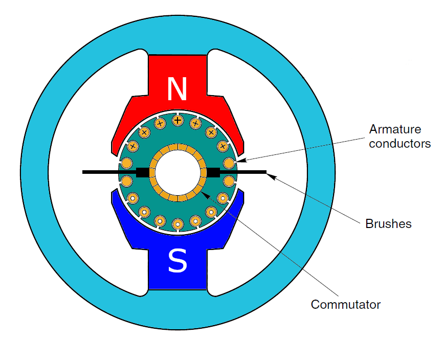
Up to now we have just looked at permanent magnet stators. These types of motors are commonly used in consumer electronics, precision laboratory instrumentation and other applications requiring relatively low power with higher efficiencies.
A limiting factor on the mechanical power generated is the magnetic field of the permanent magnets.
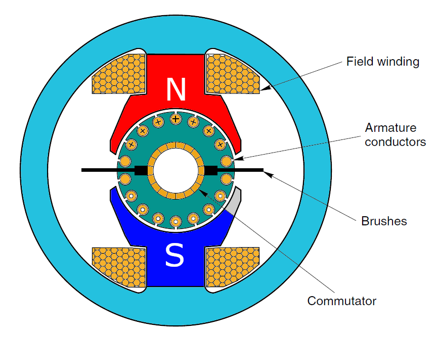
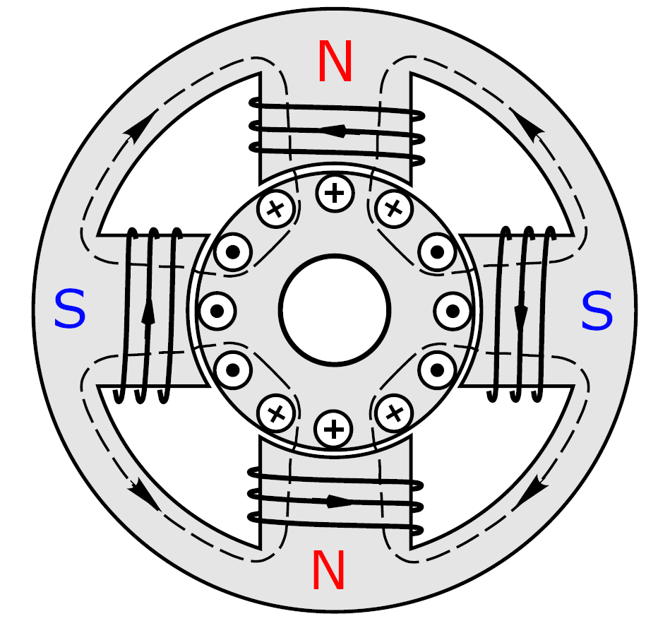
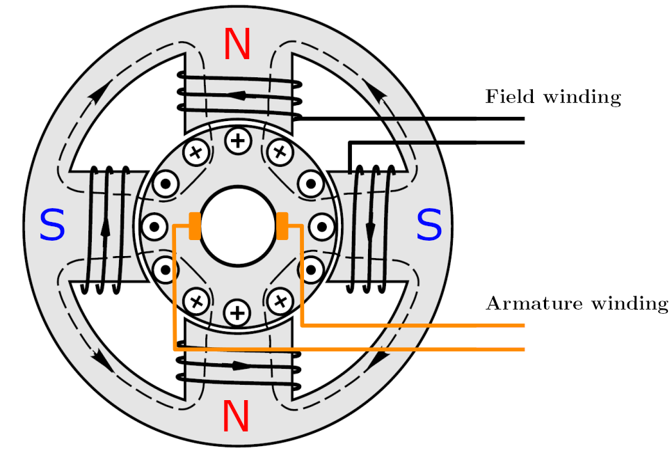
For applications where more mechanical power is required, the stators of the motor can be wound with wire and act as electromagnets, resulting in a higher magnetic flux between the poles.
| Permanent Magnet DC Motor | Field Wound DC Motor |
|---|---|
 |
 |
| 2 Pole Pair | 2 Pole Pair with Windings |
|---|---|
 |
 |
Armature and Field Connections
In general, the methods used for connecting the field and armature windings can be divided into the following groups:
- Separately excited machines — the field winding being connected to a source of supply other than the armature of its own machine.
- Self-excited machines, which may be subdivided into:
- Series-wound machines — the field winding being connected in series with the armature winding.
- Shunt-wound machines — the field winding being connected across the armature terminals.
- Compound-wound machines — a combination of shunt and series windings.
Nomenclature
| Symbol | Meaning |
|---|---|
| \(I_f\) | Field current |
| \(R_f\) | Field resistance |
| \(\varepsilon_b\) | Back e.m.f |
| \(R_a\) | Armature resistance |
| \(I_a\) | Armature current |
| \(I_s\) | Supply current |
| \(V_s\) | Supply voltage |
| \(I_{se}\) | Series current |
| \(R_{se}\) | Series field resistance |
| \(I_{sh}\) | Shunt current |
| \(R_{sh}\) | Shunt field resistance |
Reminder: Mechanical power = Input power − Electrical losses
Separately Excited DC Motor
In a separately-excited DC motor, the main field winding is excited by an external source of DC supply. The separately-excited DC motor is a doubly-excited motor, in which two sources of DC supply are required: one for the armature and the second for the excitation of the field winding.
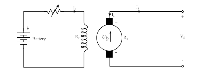
| Armature current: | \(I_a = I_s\) |
| Supply voltage: | \(V_s = \varepsilon_b + I_a R_a\) |
| Power developed in the armature: | \(P = \varepsilon_b\, I_a\) |
Series Wound DC Motor
A DC motor in which the field winding is connected in series with the armature winding is known as a series wound DC motor.
Since the series field winding carries the whole armature current, the series field winding has a small number of turns of thick wire and should possess a low resistance.
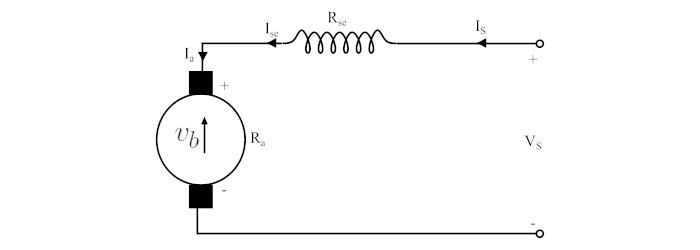
| Armature current: | \(I_a = I_{se}\) |
| Supply voltage: | \(V_s = \varepsilon_b + I_a R_a + I_{se} R_{se}\) |
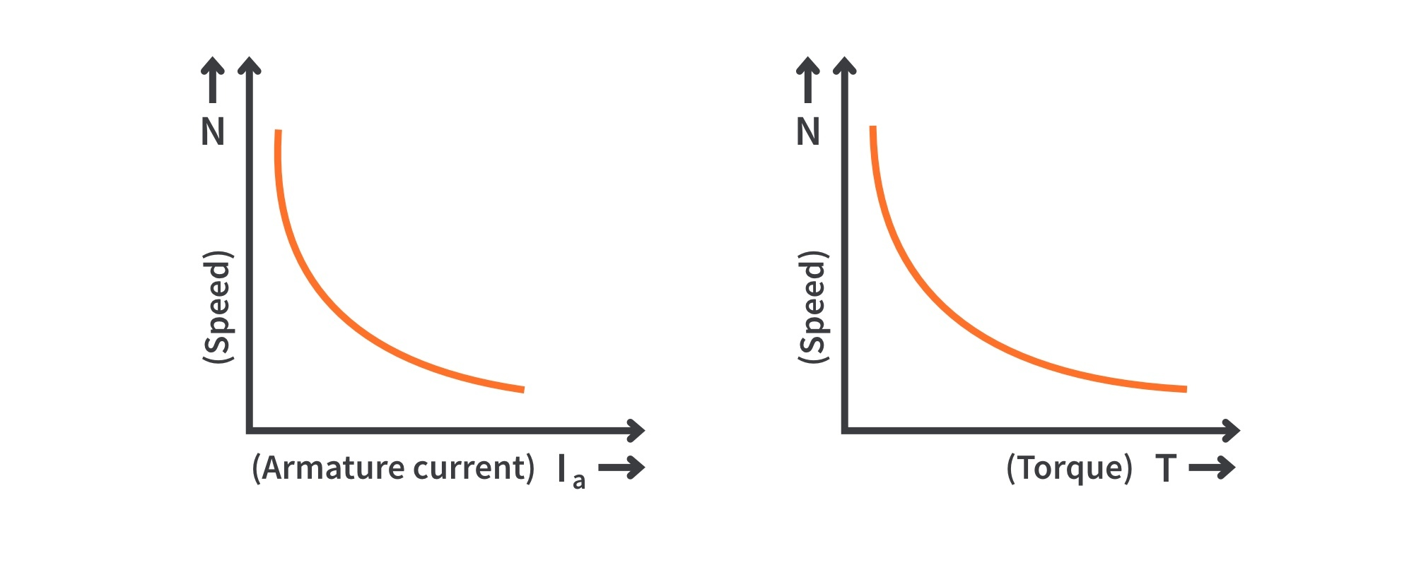
Applications — Series DC motors are variable speed motors, i.e. their speed is low at high torque and vice versa. However, at no-load or light load the motor attains a dangerously high speed. Series motors have high starting torques. Therefore, they are used in the following applications:
- Where large starting torque is required, like in elevators, electric traction, cranes, etc.
- Where the load is subjected to heavy fluctuations and the speed is required to be automatically regulated according to load requirements.
- In air compressors, vacuum cleaners, hair driers, sewing machines etc.
Shunt Wound DC Motor
A shunt wound DC motor is one in which the field winding is connected in parallel with the armature winding.
The shunt field windings are designed to have high resistance, i.e. they have a large number of turns of fine wire, so that the shunt field current is relatively small compared to the armature current.
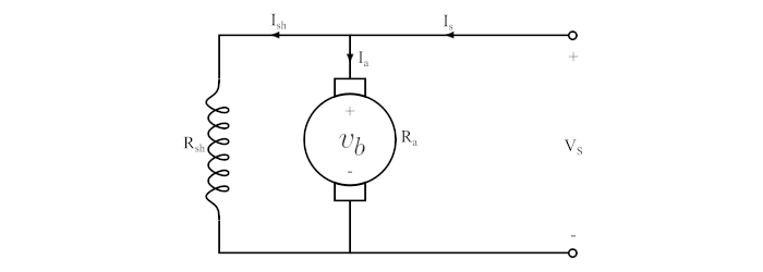
| Armature current: | \(I_a = I_s - I_{sh}\) |
| Shunt field current: | \(I_{sh} = \dfrac{V_s}{R_{sh}}\) |
| Supply voltage: | \(V_s = \varepsilon_b + I_a R_a\) |
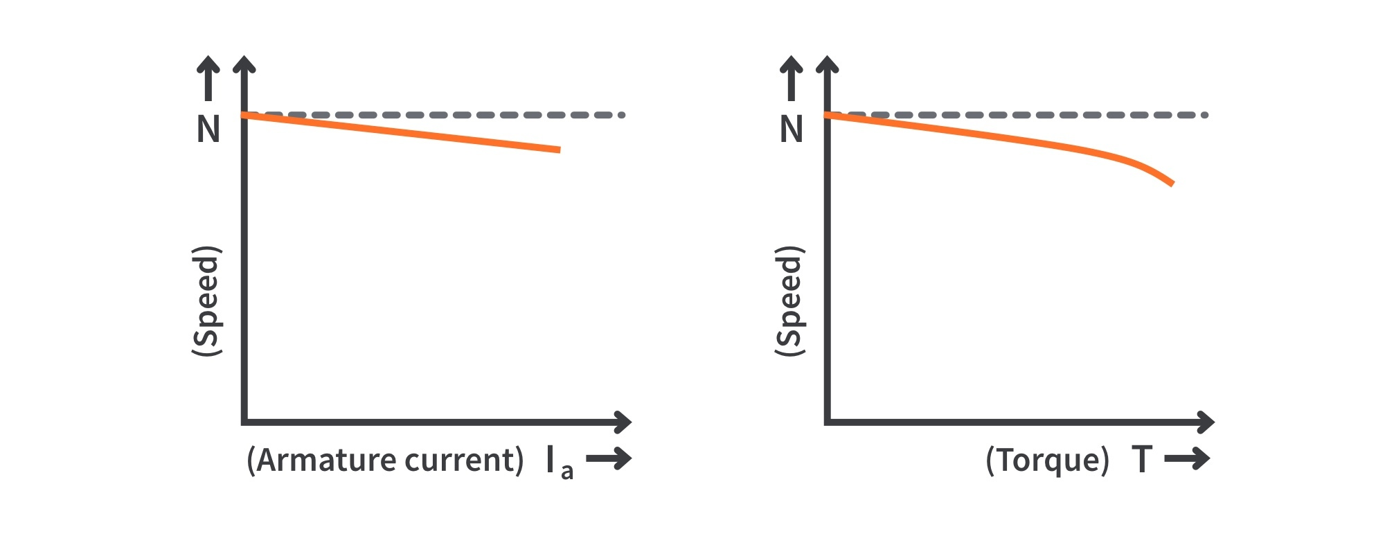
Applications — Shunt motors are constant speed motors. Therefore, they are used in the following applications:
- Where speed is required to remain constant from no-load to full load.
- In lathes, drills, shapers, spinning and weaving machines, boring mills etc.
Compound Wound DC Motor
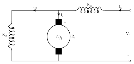
A compound motor has two field windings. One is a shunt field connected in parallel with the armature and the other is a series field that is connected in series with the armature.
| Short-shunt | Long-shunt |
|---|---|
 |
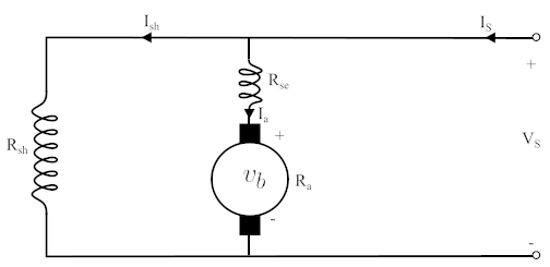 |
| In a short-shunt compound motor, the shunt field winding is directly connected in parallel with the armature winding. | When the shunt field winding is connected in parallel with the series combination of armature winding and the series field winding, the motor is known as a long-shunt compound motor. |
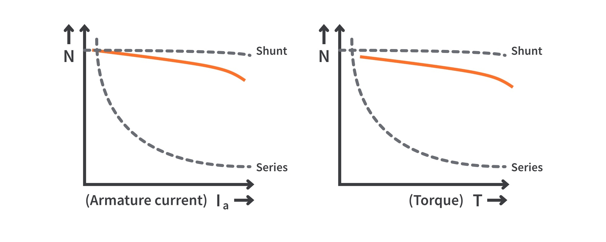
- The shunt field gives this type of motor the constant speed advantage of a regular shunt motor.
- The series field gives it the advantage of being able to develop a large torque when the motor is started under a heavy load.
- Compound motors are used in constant speed applications with irregular loads or suddenly applied heavy loads, like presses, reciprocating machines and shears etc.
Comparison: Series vs Shunt Field Winding
| Series field winding | Shunt field winding |
|---|---|
| The armature winding is in series with the field winding. | The armature winding is in parallel with the shunt field winding. |
| As the series field winding is connected in series with the armature winding, the series field carries the same current as the armature winding. | As the shunt field winding is connected in parallel with the armature winding, the voltage across the shunt field winding is the same as the armature winding. |
| The series winding is designed with few turns of thick wire. | The shunt field winding is designed with a large number of turns of thin wire. |
| The resistance of the series field winding is very low. | The resistance of the shunt field winding is very high. |
| The torque is directly proportional to the square of the armature current: \(T_m \propto \phi\, i_a\); since \(\phi \propto i_a\), \(T_m \propto i_a^2\). | The torque is directly proportional to the armature current: \(T_m \propto \phi\, i_a\); since \(\phi\) is almost constant, \(T_m \propto i_a\). |
| The starting torque developed by a series motor is high compared to a shunt motor for the same amount of armature current. | The starting torque developed by a shunt motor is low compared to a series motor for the same amount of armature current. |
| A series motor responds by decreasing its speed with a small increase in current for a given load torque. | A shunt motor holds its speed nearly constant with a large increase in input current for the same amount of load torque. |
| Variable speed motor. | Constant speed motor. |
| Applications: hoists, cranes, trolley cars, conveyors, electric locomotives. | Applications: lathes, centrifugal pumps, blowers, machine tools, printing processes, spinning machines, reciprocating pumps. |
Worked Examples
Example 1: Shunt connected DC motor
A \(230\,\text{V}\) shunt connected DC motor operates at \(1200\,\text{rpm}\). The rotor current is \(200\,\text{A}\) and the rotor coil resistance is \(0.2\,\Omega\). Rotational losses due to friction are \(500\,\text{W}\). What is the load torque?
Solution:
Draw the equivalent circuit and populate it with the known information.
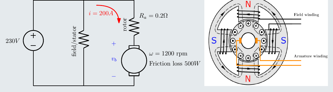
Back e.m.f.:
\[ \varepsilon_b = V_s - i_a R_a \;\Rightarrow\; 230 - 200(0.2) = 190\,\text{V} \]
Electrical power at the rotor:
\[ \varepsilon_b\, i_a \;\Rightarrow\; (190)(200) = 38\,\text{kW} \]
Mechanical power out:
\[ 38\,000 - 500 = 37\,500\,\text{W} \quad \text{or} \quad 37.5\,\text{kW} \]
Load torque:
\[ T_m = \frac{P}{\omega} \;\Rightarrow\; \frac{37\,500}{1200 \cdot \frac{\pi}{30}} = 298.4\,\text{N·m} \]
Example 2: Series connected DC motor
A \(220\,\text{V}\) series connected DC motor draws \(20\,\text{A}\) operating at \(1200\,\text{rpm}\) under load. The armature coil resistance is \(0.5\,\Omega\) and the stator winding resistance is \(1.5\,\Omega\). The rotational losses (friction etc.) are \(150\,\text{W}\). Find the output power and efficiency.
Solution:
Draw the equivalent circuit and populate it with the known information.
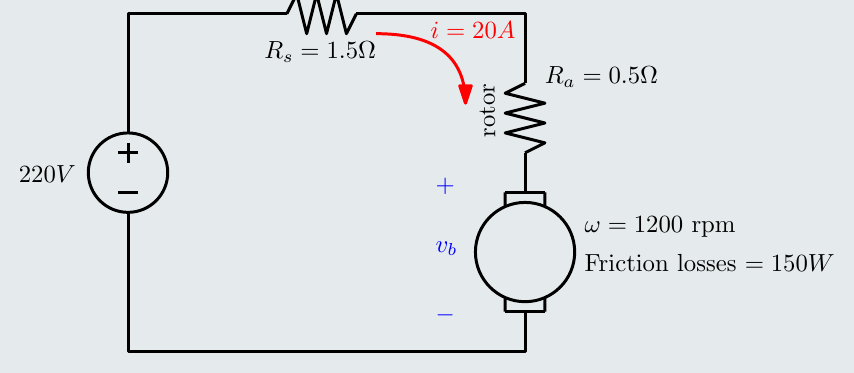
Back e.m.f.:
\[ \varepsilon_b = V_s - i_a(R_a + R_s) \;\Rightarrow\; 220 - 20(0.5 + 1.5) = 180\,\text{V} \]
Electrical power at the rotor:
\[ \varepsilon_b\, i_a \;\Rightarrow\; (180)(20) = 3.6\,\text{kW} \]
Mechanical power out:
\[ 3\,600 - 150 = 3\,450\,\text{W} \quad \text{or} \quad 3.45\,\text{kW} \]
Efficiency:
\[ \eta = \frac{P_{out}}{P_{in}} \;\Rightarrow\; \frac{3450}{(220)(20)} = 78.4\% \]
Interactive Elements
Each element below runs in the page; use Open full screen for more room.
Back emf self-regulation
A DC motor driving a variable load: increase the load and watch the speed dip, the back e.m.f. fall, the armature current and torque rise, and the motor settle at a new, slightly lower speed; then reduce the load to see the reverse.
Connection explorer
Switch between separately excited, series, shunt and compound (short and long shunt) connections; the circuit redraws with live currents and voltages, and the speed–torque and speed–current characteristics are plotted for each, showing the series motor’s dangerous no-load speed and the shunt motor’s nearly constant speed.
Worked-example calculator
The two worked examples with editable values: enter the supply voltage, currents, resistances, speed and losses and see the back e.m.f., power flow, torque and efficiency.
Knowledge Check
Q1. Explain why a DC motor is described as self-regulating.
Answer
When the load increases, the motor slows, the back e.m.f. falls, so the armature current and torque rise until the motor torque matches the load. When the load falls, the motor speeds up, the back e.m.f. rises and the current and torque fall. The motor automatically draws just enough current for the load.
Q2. Why are field windings used instead of permanent magnets in larger DC motors?
Answer
Electromagnets can produce a stronger magnetic flux between the poles than permanent magnets, so the motor can deliver more mechanical power.
Q3. Name the four ways of connecting the field and armature windings.
Answer
Separately excited, series wound, shunt wound and compound wound (short shunt or long shunt).
Q4. Why does a series field winding have few turns of thick wire, while a shunt field winding has many turns of fine wire?
Answer
The series field carries the full armature current, so it must have a low resistance (thick wire, few turns). The shunt field is connected across the full supply voltage, so it needs a high resistance to keep its current small (many turns of fine wire).
Q5. Why must a series motor never be run without a load?
Answer
Its flux is produced by the armature current. At no load the current, and so the flux, is very small, and since speed is inversely proportional to flux, the speed rises to a dangerously high value.
Q6. How does torque depend on armature current in a series motor and in a shunt motor?
Answer
Series: \(\phi \propto i_a\), so \(T_m \propto i_a^2\). Shunt: \(\phi\) is nearly constant, so \(T_m \propto i_a\).
Q7. Which motor would you choose for a crane hoist, and which for a lathe? Why?
Answer
A series motor for the hoist: high starting torque and speed that falls with load. A shunt motor for the lathe: nearly constant speed from no load to full load.
Q8. A 240 V shunt motor has an armature resistance of 0.5 Ω and draws an armature current of 20 A. What is the back e.m.f. and the power developed in the armature?
Answer
\(\varepsilon_b = V_s - I_aR_a = 240 - 20 \times 0.5 = 230\) V; \(P = \varepsilon_b I_a = 230 \times 20 = 4.6\) kW.
Q9. In a shunt motor with supply current \(I_s\), how is the armature current found?
Answer
\(I_a = I_s - I_{sh}\), where the shunt field current is \(I_{sh} = V_s/R_{sh}\).