Ladder Logic and Timers
Chapter 5 · Part I: Logic Control Fundamentals · Source: Lecture 4
5.1 Ladder logic
- Most industrial control processes use PLCs to control mechanical components such as actuators, valves and motors.
- PLCs are traditionally programmed with ladder logic diagrams, which can implement the logic gates and memory blocks from Chapter 4.
- The IEC 61131-3 standard is recommended for ladder symbols, but many vendors deviate slightly from it.
Most common symbols

Figure 5.1: Common ladder symbols.
| Symbol | Name | Meaning |
|---|---|---|
—| |— |
Input contact | A switch, relay, photoelectric sensor etc., i.e. anything that gives an on/off signal |
—( )— |
Output load (coil) | A motor, valve, actuator, solenoid, alarm etc. |
—|/|— |
Inverse input | If the input is A, this uses \(\overline{A}\) (NOT A) |
AND and OR in ladder form
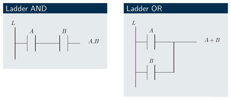
Figure 5.2: Contacts in series = AND (\(A.B\)); contacts in parallel = OR (\(A + B\)).
Rules
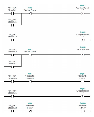
Figure 5.3: A multi-rung ladder program.
- The left rail can be regarded as live (L) and the right as neutral, so every rung must contain a load or output to avoid a short circuit.
- Inputs can be repeated on as many rungs as needed.
- An output can be created only once.
- The on/off state of an output can be used as an input; the symbol shows the output/input nature of the variable.
- Variables are only updated at the end of a scan cycle: all rungs are processed, then all variables are updated.
5.2 Start logic and latching
Start logic. When Go button G is pressed, output P is energised (often to turn on a machine). When G is released, the power goes off.
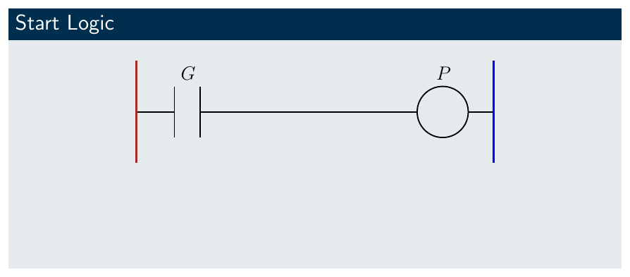
Figure 5.4: Start logic.
The state of G depends on the mechanical action of the switch. Most industrial systems use push buttons for Start and Stop. Why might this be? (After a power loss, a push-button system won’t restart by itself when power returns.)
How can P be kept on after G is released?
Latching. A contact of P is placed in parallel with G, so the output latches itself on when ORed with G.
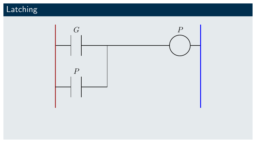
Figure 5.5: Self-latching output.
The system now needs a stop function. Where should the Stop switch go?
Latching with stop. With NOT S in series, output P is interrupted when Stop button S is pressed:
\[P = (G + P).\overline{S}\]
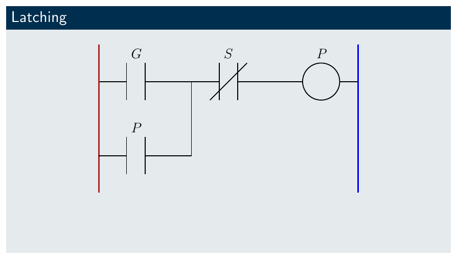
Figure 5.6: Latch with stop.
The Stop input is wired normally closed. Why might this be? A broken wire or failed contact then looks the same as pressing Stop, so the system fails safe.
Lock and switch example, from Chapter 2: two parallel branches, \(\overline{L}.P\) and \(L.S\), driving P.
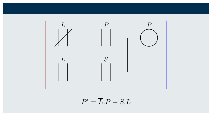
Figure 5.7: \(P' = \overline{L}.P + S.L\) as a ladder diagram.
5.3 Timers: the conveyor reject example
A conveyor rejects overweight items. If an item is detected as overweight by sensor A, trap door Y opens immediately and stays open for 4 seconds.
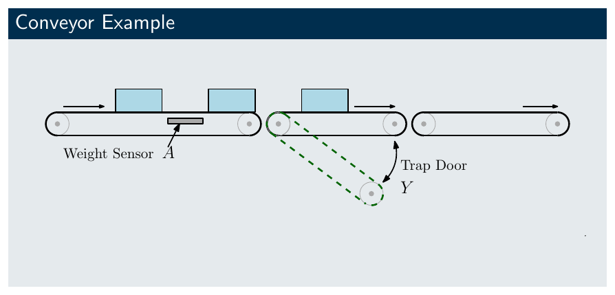
Figure 5.8: Conveyor reject station.
An On-Delay Timer (TON) is used. PLCs offer many timers; TON and the Off-Delay Timer (TOF) are the most common.
- TON: the output goes high a preset time (here 4 s) after the input goes high. When the input goes low, the output goes low and the timer resets.
- TOF: the output goes high immediately with the input and stays high for a preset time after the input goes low.
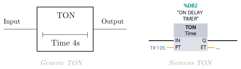
Figure 5.9: Generic TON block and the Siemens TON block.
Designing the logic:
- Because of how the TON works, sensor A can’t start the timer directly: A goes low once the item has passed the weigh station, resetting the timer to zero.
- Instead, use output Y, switched on by A and latched on by itself.
- To switch Y off, an interrupt NOT B is needed, where B is the output of the 4 s timer, started by Y.
Rung 1:  ( A OR Y ) AND NOT B  ──> (Y)
Rung 2:  Y ──> [TON 4 s] ──> B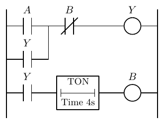
Figure 5.10: Ladder solution.
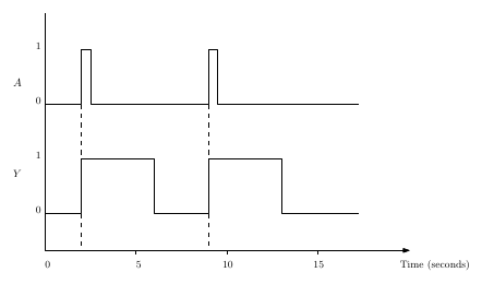
Figure 5.11: Response diagram. Each detection of A gives a 4 s pulse on Y.
Key points
- Series = AND, parallel = OR, inverse contact = NOT.
- A latch is an output contact in parallel with its start condition; a normally closed Stop in series breaks it.
- A TON needs a sustained input, so latch the output and use the timer output to unlatch it.
Interactive applets
Each applet runs in the page; use Open full screen for more room, or open all of this chapter’s applets together.
Applet 5.1 · Ladder logic editor and simulator
Build rungs from contacts, inverse contacts, coils and TON/TOF blocks; run the program with clickable inputs and watch “power flow” animate along each rung, scan by scan.
Teaches: Ladder syntax, scan-cycle evaluation and rule checking (it flags rungs without a load and duplicate coils). · Open full screen ↗
Applet 5.2 · Latch and Stop wiring lab
Choose a normally open or normally closed Stop contact and push buttons or toggle switches, then simulate a broken wire or power cut and see which configuration fails safe.
Teaches: The “why” questions on the slides. · Open full screen ↗
Applet 5.3 · TON vs TOF timing sandbox
Drive a timer input with a draggable waveform, adjust the preset, and see output and elapsed time (ET) plotted for TON and TOF side by side.
Teaches: Timer semantics, and why the conveyor needs a latch. · Open full screen ↗
Applet 5.4 · Conveyor reject animation
Boxes of random weight travel along a belt; the learner’s ladder program drives the trap door, and the applet counts correct and incorrect rejections.
Teaches: Testing a design against a live process. · Open full screen ↗