Network Protocols: OSI, TCP/IP and Data Integrity
Chapter 11 · Part III: Industrial Communications · Source: Lecture 9
11.1 The OSI reference model
- To encourage standardisation in network design, the International Standards Organization (ISO) established a reference model that describes networks in terms of layers of responsibility: Open Systems Interconnection (OSI).
- It divides the communication problem into a stack of sub-problems, or layers.
- Each layer deals only with the layer directly above or below it.
- Outgoing (sent) messages move down the stack; incoming (received) messages move up.
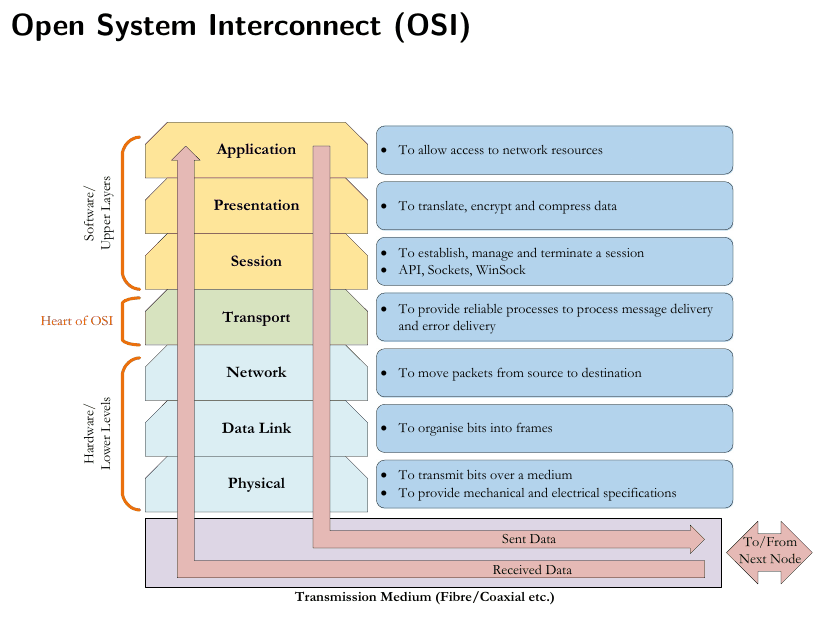
Figure 11.1: The OSI model.
| # | Layer | Role | Addressing / device | Group |
|---|---|---|---|---|
| 7 | Application | Allow access to network resources | Software / upper layers | |
| 6 | Presentation | Translate, encrypt and compress data | Software / upper layers | |
| 5 | Session | Establish, manage and terminate a session (API, sockets, WinSock) | Software / upper layers | |
| 4 | Transport | Reliable process-to-process delivery and error recovery | Ports | Heart of OSI |
| 3 | Network | Move packets from source to destination | IP addresses; routers | Hardware / lower layers |
| 2 | Data link | Organise bits into frames | MAC addresses; switches | Hardware / lower layers |
| 1 | Physical | Transmit bits over a medium; mechanical and electrical specifications | Cables, hubs, repeaters | Hardware / lower layers |
The layers in detail

Physical layer. Defines voltage levels, baud rate, the hardware used at nodes and the transmission medium. Transmission separate from reception is half duplex; simultaneous transmission and reception is full duplex.

Data link layer. Interacts with the wired or wireless signals (the physical layer) through network interface cards. It finds the physical address on the network, the MAC address: a 48-bit address (12 hex digits) specific to a piece of hardware. It passes only valid messages up to the next layer, establishes whether a message is for this node, and can check data integrity. Switches are layer-2 devices. Layer 2 handles hop-to-hop (device-to-device) delivery.

Network layer. Finds the shortest path (usually the shortest time) to the destination. It adds information to the packet when two or more LANs are connected by a router. The addressing scheme is the IP address, a 32-bit number written as 4 octets (0–255 each). Routers and hosts are layer-3 devices. The network layer handles end-to-end delivery.
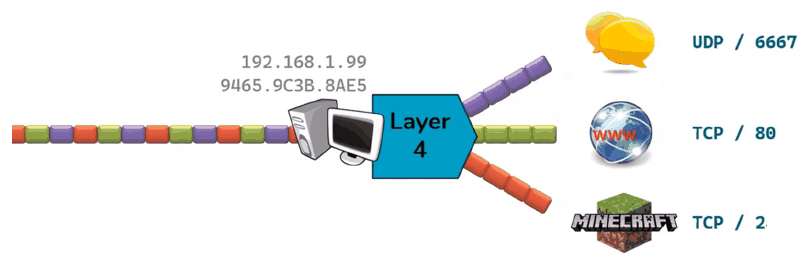
Transport layer. Service-to-service delivery: it guarantees end-to-end transmission of data. It checks whether the destination exists, whether the recipient received the data, and whether incoming data is intact or corrupted. It divides data into packets, coordinates their transmission and reception, and sets the transmission rate to suit a slower recipient.
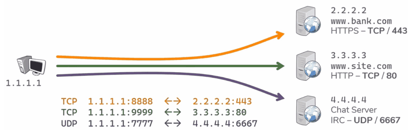
The transport layer’s addressing scheme is ports, 0–65535 for both TCP and UDP. Servers listen for requests on predefined ports (e.g. HTTP 80, HTTPS 443); clients pick a random port for each connection.
Session layer. Looks after user-specific needs such as passwords. It defines the user’s rights and permissions (which software functions are available) and groups information appropriately for the user.
Presentation layer. Converts data between computers that use different encodings at the application layer. Data often generated as ASCII is converted to binary before transmission. Encryption and compression also happen here.
Application layer. User-specific data and applications that use the network, e.g. email, web browsers, file sharing, print servers, network drives and social media.
Not every layer is always needed: if all stations are on one LAN and use the same application protocols, the network, transport, session and presentation layers can be dropped.
11.2 TCP/IP
OSI is just a model. Its most common real-world form is TCP/IP (Transmission Control Protocol / Internet Protocol).

Figure 11.2: Mapping OSI’s seven layers onto TCP/IP’s four.
| TCP/IP layer | Notes / protocols |
|---|---|
| Application | Depends on the application, e.g. HTTP or HTTPS for web browsing. Logging in to a server over HTTP is effectively a session layer; HTTPS encryption effectively adds a presentation layer. |
| Transport | TCP guarantees end-to-end delivery. UDP has no checks; error checking is left to the upper layers. |
| Internet | IP (Internet Protocol), ICMP (Internet Control Message Protocol) |
| Network access | Combines the data link and physical layers: Ethernet, fieldbus, Wi-Fi, ISDN, plus cabling, connectors etc. |
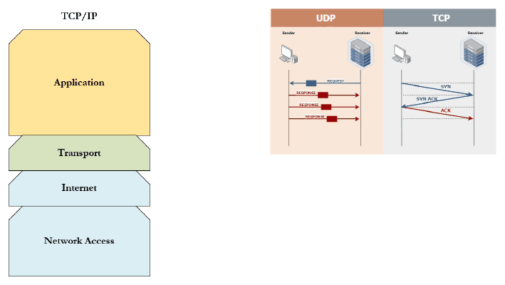
Figure 11.3: TCP (acknowledged, ordered delivery) vs UDP (fire and forget).
Encapsulation
As data passes down the stack, each layer adds a header:
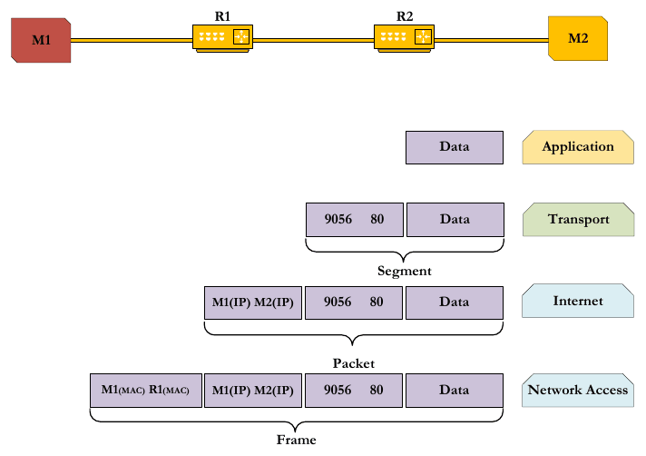
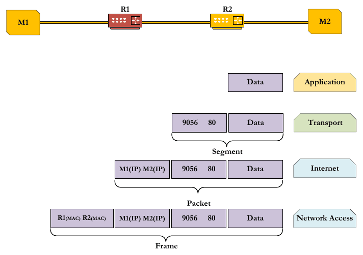
- Transport: adds source and destination ports (e.g. 9056 → 80), forming a segment.
- Internet: adds source and destination IP addresses (M1(IP) → M2(IP)), forming a packet.
- Network access: adds source and destination MAC addresses and a trailer, forming a frame.
As the frame hops between machines and routers (M1 → R1 → R2 → M2), the MAC addresses change at every hop while the IP addresses and ports stay the same. At the receiving machine the headers are stripped off in reverse order.
| Hop M1 → R1 | Hop R1 → R2 | Hop R2 → M2 |
|---|---|---|
 |
 |
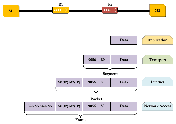 |
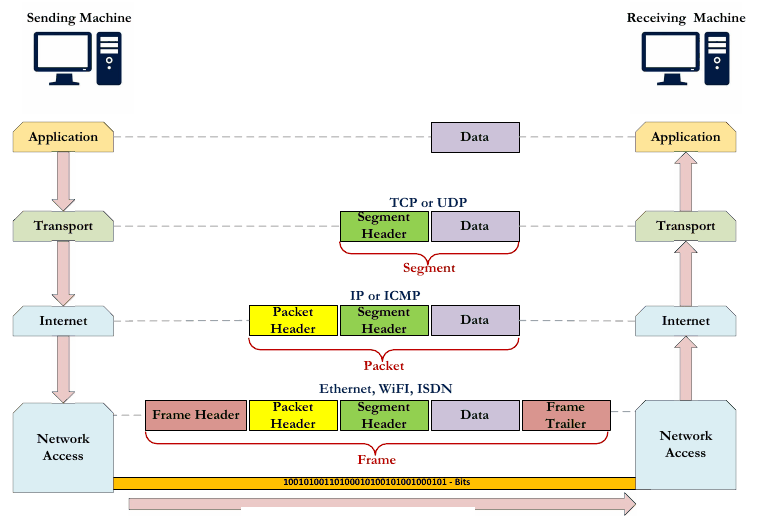
Figure 11.4: Full encapsulation and de-encapsulation from sender to receiver.
Header formats
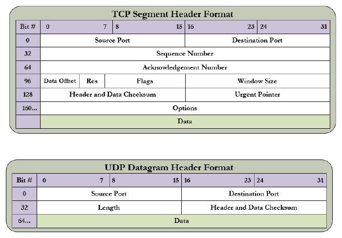
Figure 11.5: Transport-layer headers: TCP segment (top) and UDP datagram (bottom).
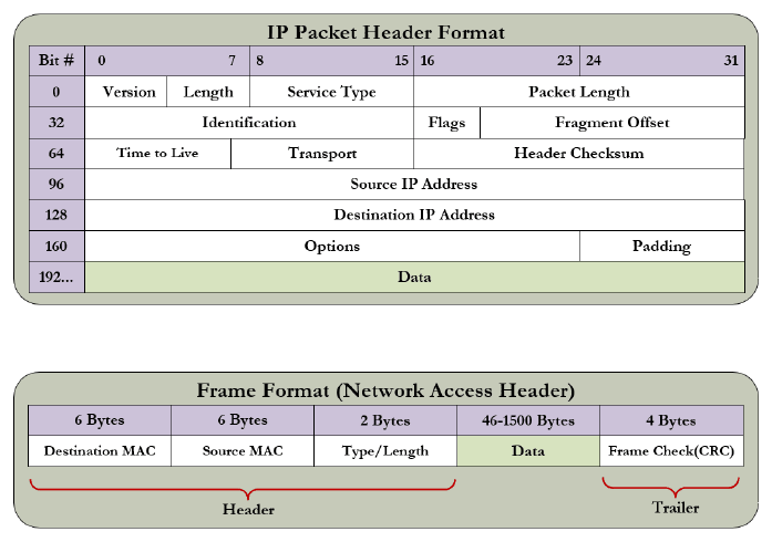
Figure 11.6: IP packet header and network-access (Ethernet) frame format.
11.3 Data integrity
Data integrity is checked at several levels.
Checksum (transport and internet layers, headers only)
The data words are added with end-around carry (any carry out of the top bit is added back in at the bottom), and the checksum is the one’s complement of the sum.
| Step | Value |
|---|---|
| Data words | 10011001, 11100010, 00100100, 10000100 |
| 10011001 + 11100010 | 1 01111011 → wrap carry → 01111100 |
| + 00100100 | 10100000 |
| + 10000100 | 1 00100100 → wrap carry → 00100101 |
| Sum | 00100101 |
| Checksum (complement) | 11011010 |
The receiver adds the received data and checksum: 00100101 + 11011010 = 11111111. Its complement is 00000000, so it accepts the data.
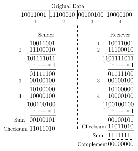
Figure 11.7: Sender and receiver checksum calculations.
Cyclic Redundancy Check (network access layer, whole frame)
- Original data: 1010000
- Generator polynomial: \(x^3 + 1\), i.e. \(1x^3 + 0x^2 + 0x^1 + 1x^0\) → generator 1001
- For an n-bit CRC generator, append n − 1 zeros to the message: 1010000000
- Repeatedly XOR the generator down the message (modulo-2 division); the remainder is 011.
- Transmitted data: 1010000011
- The receiver divides the received data by 1001; a remainder of 000 means accept.
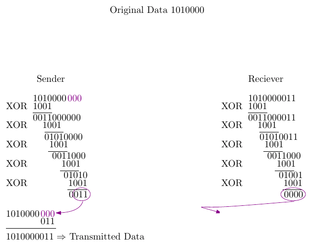
Figure 11.8: CRC calculation at the sender and the check at the receiver.
Key points
- OSI: 7 layers; TCP/IP: 4 layers. Addresses are MAC (layer 2, hop-to-hop), IP (layer 3, end-to-end) and port (layer 4, service-to-service).
- Encapsulation: segment, then packet, then frame. MACs change per hop; IP addresses and ports don’t.
- Checksums (one’s complement) protect headers; a CRC (polynomial division) protects the whole frame.
Interactive applets
Each applet runs in the page; use Open full screen for more room, or open all of this chapter’s applets together.
Applet 11.1 · Encapsulation explorer
Type a message and press Send; it drops down the stack gaining coloured headers, then hops M1 → R1 → R2 → M2 with the MAC fields rewritten at each hop, and is unwrapped at the receiver. Pause and inspect any header.
Teaches: Segment, packet and frame; which addresses change per hop. · Open full screen ↗
Applet 11.2 · OSI layer sorter
Drag protocols and devices (HTTP, TCP, IP, Ethernet, switch, router, hub, MAC, port 443) onto the right layer, with instant feedback.
Teaches: Layer responsibilities and addressing schemes. · Open full screen ↗
Applet 11.3 · Checksum calculator with error injection
Enter 8-bit words; the applet shows the binary addition with wrap-around carries step by step. Flip a bit “in transit” and see whether the receiver detects it.
Teaches: One’s-complement checksums and their limits (e.g. some two-bit errors cancel out). · Open full screen ↗
Applet 11.4 · CRC long-division animator
Enter the data and generator polynomial; each XOR step animates, appending the remainder. The learner then corrupts bits and runs the receiver check.
Teaches: Modulo-2 division and CRC’s strength against burst errors. · Open full screen ↗
Applet 11.5 · TCP vs UDP race
Send a stream over a lossy link: TCP retransmits and reorders (slower but complete), while UDP is fast but has gaps.
Teaches: Choosing a transport for control data vs video, etc. · Open full screen ↗