Design Case Studies: Cooling System and Gas Furnace
Chapter 6 · Part I: Logic Control Fundamentals · Source: Lecture 5
These two examples bring together response diagrams, logic networks and ladder logic.
6.1 Example 1: machine cooling system
Requirements
- Machine Y is turned on and off with a toggle switch A.
- The machine needs cooling Z, which runs for 3 minutes after the machine is switched off.
Task: design the control logic for the machine and the cooling, using a timer where appropriate.
| Inputs | Outputs |
|---|---|
| A = 0 machine switched off | Y = 0/1 machine off/on |
| A = 1 machine switched on | Z = 0/1 fan off/on |
Response diagram
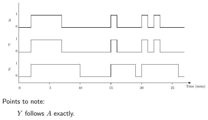
Figure 6.1: Response diagram for the cooling system.
Points to note:
- Y follows A exactly.
- Z stays on for 3 minutes after A turns off.
- The sequence after 20 minutes shows that Z is timed from the final switching-off of A.
Logic network
- \(Y = A\)
- \(Z = A\) OR (within 3 minutes after \(A\) goes off)
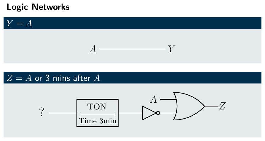
Figure 6.2: Building the logic network.
While a TON is timing, its output is low, so to keep Z on during this time the timer output must be negated. The timer starts when A switches off, so NOT A (\(\overline{A}\)) starts it.
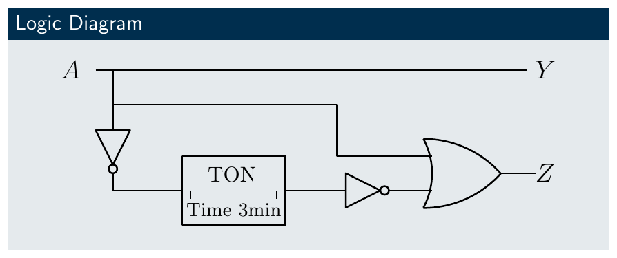
Figure 6.3: Complete logic diagram.
Ladder logic
You can start from scratch or translate the logic network. The OR inputs to Z are A and a NOT function; because it is a NOT, use a normally closed contact. That NOT is the output D of a timer triggered by NOT A:
Rung 1:  A ──────────────> (Y)
Rung 2:  A OR NOT D ─────> (Z)
Rung 3:  NOT A ──> [TON 3 min] ──> D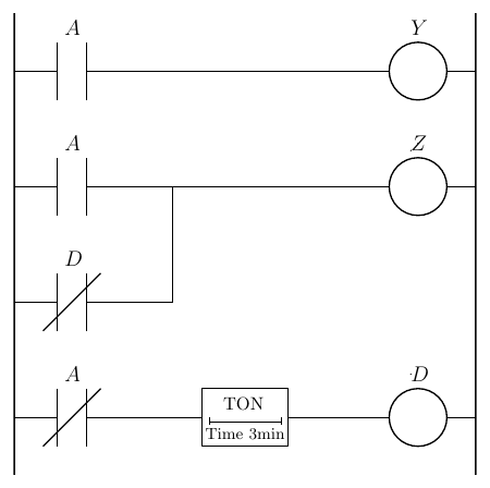
Figure 6.4: Complete ladder solution.
Exercise: investigate how a TOF timer works and implement the same logic with it. (Hint: a TOF driven directly by A gives Z in a single rung.)
6.2 Example 2: gas furnace
A gas-fuelled furnace heats blanks before forging.
- A flame detection system F detects that the furnace is firing.
- The power command P is switched manually.
- On start-up, or if the flame goes out, the ignition system I is switched on until the flame appears or 5 seconds pass.
- If no flame appears after 5 seconds, the gas G is turned off and an alarm A is switched on.
Design the logic to control the system.
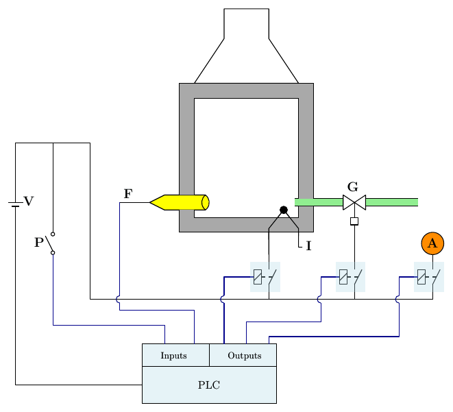
Figure 6.5: Gas furnace control system.
| Inputs | Outputs |
|---|---|
| P = 0/1 power off/on | G = 0/1 gas valve closed/open |
| F = 0/1 flame off/on | I = 0/1 ignition off/on |
| A = 0/1 alarm off/on |
Inputs and outputs are defined relative to the control system. Fuel is an input to the furnace, but the signal to the gas valve is an output from the controller.
Response diagram scenarios
- Turn the power on, with no flame until 3 seconds later.
- A momentary loss of flame, which reappears when the right action occurs.
- An extended loss of flame, after which the power is turned off manually.
- A spurious short flame signal while the power is off.
- Switch the system on, but no flame appears even after 5 seconds.
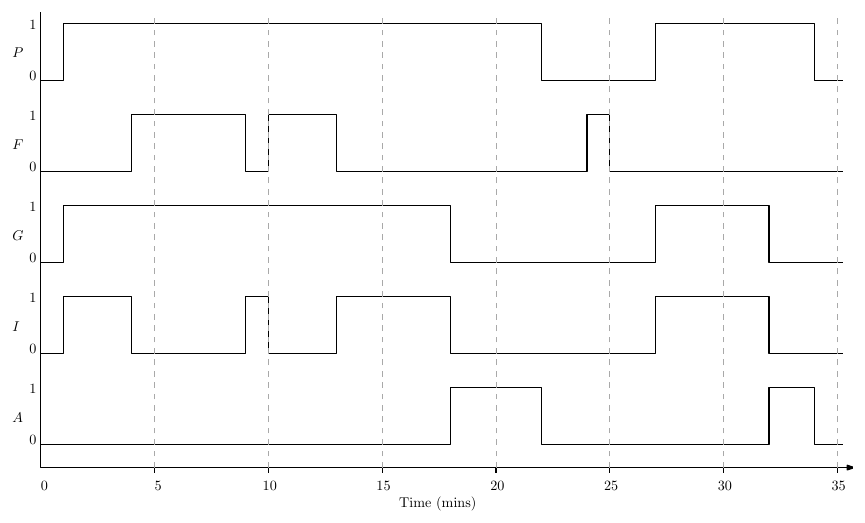
Figure 6.6: Response diagram covering all five scenarios.
Logic network development (working back from the outputs)
Gas G is on when (1) both power and flame are on, or (2) power is on and the ignition is trying to fire.

Figure 6.7: Gas valve logic.
Ignition I is on if (1) power P is on and (2) no flame is detected and (3) the time limit hasn’t been exceeded.
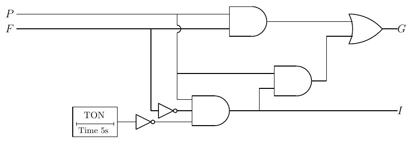
Figure 6.8: Ignition logic.
The timer starts when power P is on and there is no flame F. The alarm A is on when power P is on and there is no flame and 5 seconds have passed.

Figure 6.9: Complete logic network.
\[G = P.(F + I) \qquad I = P.\overline{F}.\overline{A} \qquad A = \text{TON}_{5\,s}(P.\overline{F})\]
Ladder logic
Literal translation of the logic network:
Rung 1:  P AND ( F OR I ) ─────────> (G)
Rung 2:  P AND NOT F AND NOT A ────> (I)
Rung 3:  P AND NOT F ──> [TON 5 s] ──> A
Figure 6.10: Literal ladder translation.
Ladder logic sometimes allows further simplification, but don’t oversimplify and leave the design intent unclear to whoever reads your code later. Here, for I to be high P must already be high, so P doesn’t need to be ANDed explicitly with the I branch on the G rung:
Rung 1: ( P AND F ) OR I ─────────> (G)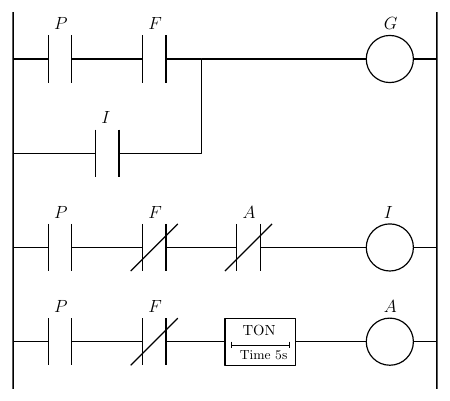
Figure 6.11: Simplified ladder.
Key points
- Work from requirements, to I/O list, to response diagram, to logic network, to ladder.
- A timer’s output is low while it times; negate it where the output must stay on during the delay.
- Simplify ladders only where intent stays obvious.
Interactive applets
Each applet runs in the page; use Open full screen for more room, or open all of this chapter’s applets together.
Applet 6.1 · Cooling fan simulator (TON vs TOF)
Flip the machine switch and watch a fan animation and a 3-minute countdown (time can be sped up); switch between the TON + NOT design and a single-TOF design and compare the response plots.
Teaches: Equivalence of the two timer approaches. · Open full screen ↗
Applet 6.2 · Gas furnace scenario player
Pick one of the five scenarios (or script a custom one); the applet animates flame, igniter, gas valve and alarm, and plots a live response diagram from the learner’s ladder program.
Teaches: Validating a design against every scenario, including the spurious-flame edge case. · Open full screen ↗
Applet 6.3 · Fault injection challenge
Inject faults (flame sensor stuck on or off, ignition failure) and see whether the design shuts the gas off safely; it scores fail-safe behaviour.
Teaches: Safety thinking beyond the nominal design. · Open full screen ↗
Applet 6.4 · Logic-to-ladder translator
Click a gate in the logic network and the matching ladder elements highlight (and vice versa).
Teaches: The mapping between the two representations. · Open full screen ↗