Lecture 7: Capacitors and Inductors
Introduction
- Before looking in depth at alternating current and voltage applications, it is worth spending some time describing the DC transient effects of some standard components.
- In this lecture we briefly look at the role of capacitors and inductors in circuits, and how they behave in response to DC and square-wave inputs.
- We then look at some nomenclature for sine waves that is used throughout this course.
- Finally, we look at the AC (sine-wave) response of these components, with a particular emphasis on frequency.
Capacitors: DC Response
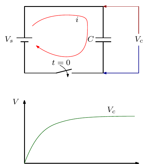
- A common component in electrical systems.
- Used to store energy or to protect against voltage spikes.
- The voltage build-up across the capacitor depends on time.
- The current is given by
\[ i = C\,\frac{dV_c}{dt} \]
- This means that when \(V_c\) settles, no current flows.
- For a capacitor, current is present before the voltage builds up.
Switching at increasing frequency
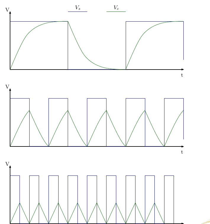
- As DC is switched with increasing frequency, the voltage build-up across the capacitor becomes less pronounced.
- In effect, as the frequency increases the capacitor acts more and more like a short circuit.
- With increasing frequency, the overall voltage drop is reduced.
- If there is no voltage drop, there is no “impedance” or “resistance” to current flow in the circuit.
Inductors: DC Response
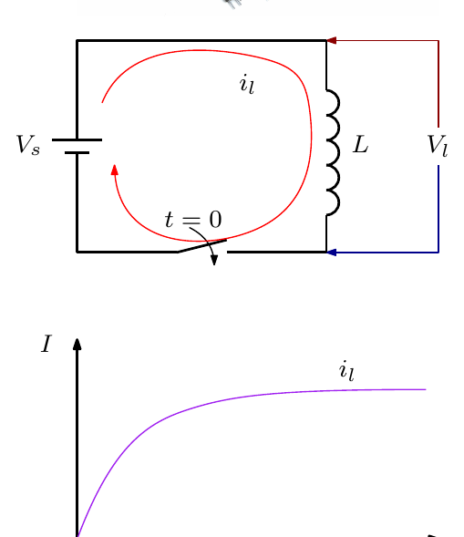
- A common component in electrical systems: effectively a coil of wire, similar to what you have seen in an armature.
- The current through the inductor depends on time.
- The voltage across the inductor is
\[ V_l = L\,\frac{di_l}{dt} \]
- This means that when \(i_l\) settles, there is no voltage across the inductor.
- For an inductor, current is present after the voltage builds up.
Switching at increasing frequency
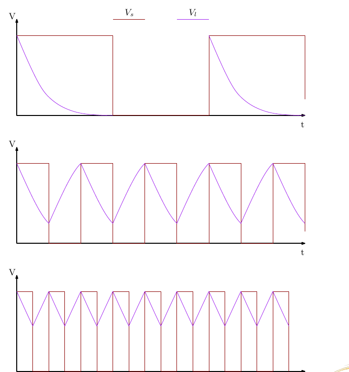
- As DC is switched with increasing frequency, the voltage across the inductor does not reach zero.
- In effect, as the frequency increases the inductor acts more and more like an open circuit.
- With increasing frequency, the overall voltage drop is increased.
- An increased voltage drop means increased “impedance” or “resistance” to current flow in the circuit.
Summary
| Capacitors | Inductors |
|---|---|
| \(i = C\,\dfrac{dV_c}{dt}\) | \(V_l = L\,\dfrac{di_l}{dt}\) |
| With increasing frequency the capacitor acts more and more like a small resistance or impedance (short circuit). | With increasing frequency the inductor acts more and more like a large resistance or impedance (open circuit). |
| Voltage lags current in a purely capacitive circuit: it takes time for the voltage to build up. | Voltage leads current in a purely inductive circuit: there is a voltage across the inductor before current flows. |
Sine Wave Description
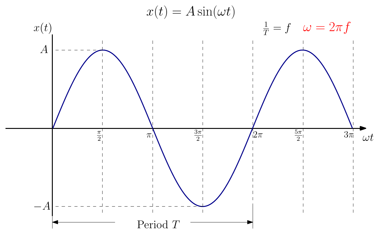
\[ x(t) = A\sin(\omega t), \qquad T = \frac{1}{f}, \qquad \omega = 2\pi f \]
where \(A\) is the amplitude, \(f\) the frequency (Hz), \(T\) the period (s) and \(\omega\) the angular frequency (rad/s).
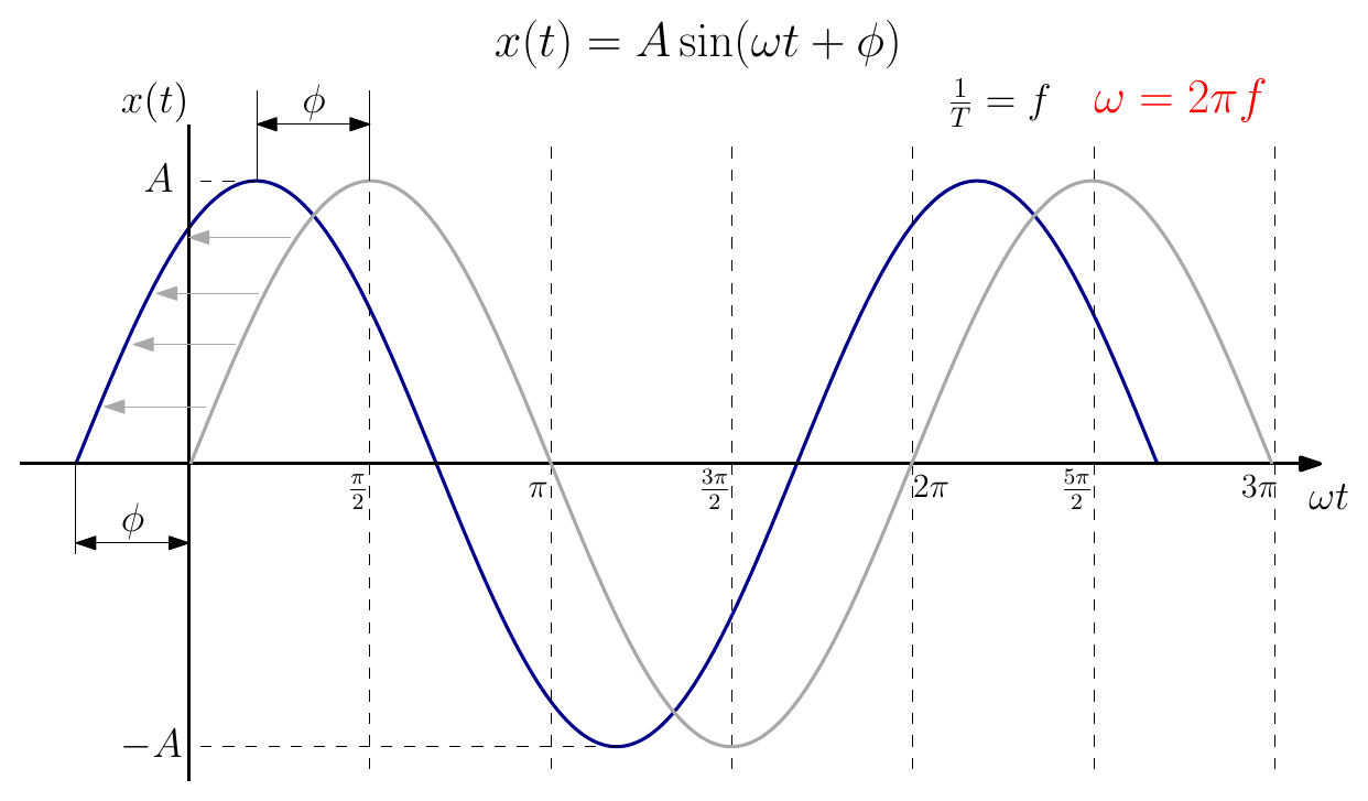
A sine wave can also be shifted by a phase angle \(\varphi\):
\[ x(t) = A\sin(\omega t + \varphi) \]
AC Response of a Resistor
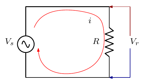
Since \(V_s = A\sin(\omega t)\) and \(i = \dfrac{V_s}{R}\),
\[ i = \frac{A\sin(\omega t)}{R} = \frac{A}{R}\sin(\omega t) \]
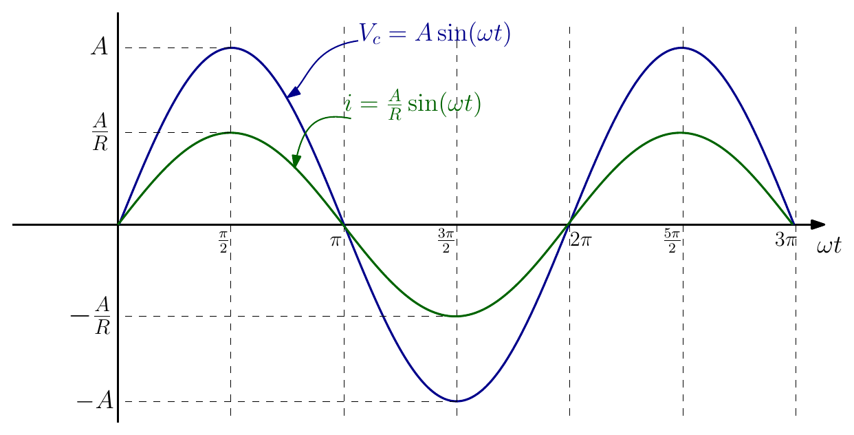
Looking at the expression for the current \(i\):
- The current is at the same frequency \(\omega\) as the input voltage.
- The waves are in phase.
AC Response of a Capacitor
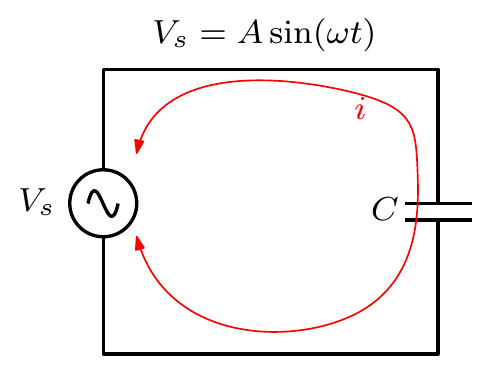
Since \(V_s = A\sin(\omega t)\) and \(i = C\,\dfrac{dV_s}{dt}\),
\[ i = C\,\frac{d\big(A\sin(\omega t)\big)}{dt} = A\,C\,\omega\cos(\omega t) \]
Looking at the expression for the current \(i\):
- The current is at the same frequency \(\omega\) as the input voltage.
- The magnitude of the current (\(AC\omega\)) changes with frequency.
- The waves are out of phase by 90°.
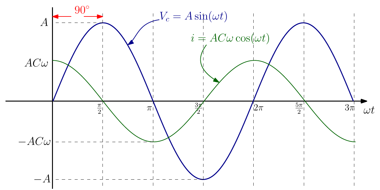
For an AC capacitor response we say that current leads voltage. In a purely capacitive circuit, current leads voltage by 90°.
Capacitive reactance \(X_C\)
Taking the magnitude of each wave, \(i = AC\omega\) and \(V_s = A\):
\[ \frac{V_s}{i} = \frac{A}{AC\omega} = \frac{1}{\omega C} = \frac{1}{2\pi f C} \]
\[ X_C = \frac{1}{2\pi f C} \]
- \(X_C\) is called the capacitive reactance.
- The reactance depends on frequency: it falls as frequency rises, which is the effect seen with the square waves above.
- In the DC case, \(\dfrac{V}{I} = R\), the resistance. In AC we use the term impedance to capture both the resistance and the reactance of components.
- \(X_C\) can be considered as an impedance to current flow, and has units of Ω.
AC Response of an Inductor
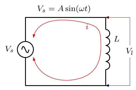
Taking the current as \(i = A\sin(\omega t)\), and since \(V_l = L\,\dfrac{di}{dt}\),
\[ V_l = L\,\frac{d\big(A\sin(\omega t)\big)}{dt} = A\,L\,\omega\cos(\omega t) \]
Looking at the expression for the voltage across the inductor \(V_l\):
- The voltage is at the same frequency \(\omega\) as the current.
- The magnitude of the voltage (\(AL\omega\)) changes with frequency.
- The waves are out of phase by 90°.
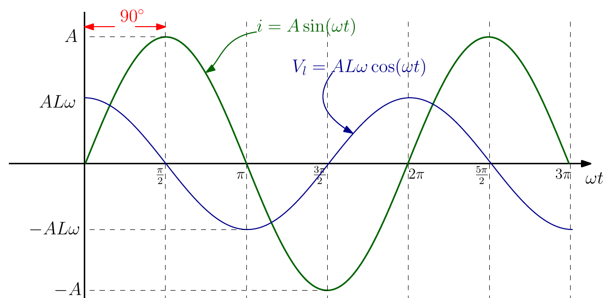
For an AC inductive response we say that current lags voltage. In a purely inductive circuit, current lags voltage by 90°.
Inductive reactance \(X_L\)
Taking the magnitude of each wave, \(V_l = AL\omega\) and \(i = A\):
\[ \frac{V_l}{i} = \frac{AL\omega}{A} = \omega L = 2\pi f L \]
\[ X_L = 2\pi f L \]
- \(X_L\) is called the inductive reactance.
- The reactance depends on frequency: it rises as frequency rises, which is the effect seen with the square waves above.
- As with the capacitor, \(X_L\) can be considered as an impedance to current flow, and has units of Ω.
Interactive Elements
Each element below runs in the page; use Open full screen for more room.
Square-wave RC and RL explorer
A square-wave source switching an RC or RL circuit, with a frequency slider (or slider for the time constant). Students see the capacitor voltage stop reaching the supply, or the inductor voltage stop decaying to zero, as the frequency rises: the lecture’s three-frequency figures, but continuous.
Sine-wave anatomy
Sliders for amplitude \(A\), frequency \(f\) and phase \(\varphi\), with \(T\) and \(\omega\) worked out and the wave redrawn live; the phase shift is shown as a time and as an angle.
R, L and C on AC
Pick a resistor, capacitor or inductor, set the frequency and component value, and watch the voltage and current waves (and a rotating phasor pair) with the 0° or 90° lead/lag highlighted, plus the reactance \(X_C = 1/(2\pi f C)\) or \(X_L = 2\pi f L\).
Reactance against frequency
A plot of \(X_C\) and \(X_L\) against frequency with a draggable frequency marker, showing \(X_C\) falling towards a short circuit and \(X_L\) rising towards an open circuit, and where the two cross.
Knowledge Check
Q1. When a DC supply is first switched onto a capacitor, which comes first: the current or the voltage across the capacitor?
Answer
The current. \(i = C\,dV_c/dt\), so the current is largest when the voltage is changing fastest (at switch-on); the voltage then builds up over time and the current falls to zero when \(V_c\) settles.
Q2. As the switching frequency of a square wave increases, does an inductor behave more like a short circuit or an open circuit?
Answer
More like an open circuit: its voltage no longer decays to zero, so it drops more voltage and offers more impedance to current. (A capacitor does the opposite, behaving more like a short circuit.)
Q3. A sine wave has a frequency of 50 Hz. What are its period and angular frequency?
Answer
\(T = 1/f = 1/50 = 20\) ms, and \(\omega = 2\pi f = 2\pi \times 50 \approx 314\) rad/s.
Q4. In a purely capacitive AC circuit:
- current and voltage are in phase
- current lags voltage by 90°
- current leads voltage by 90°
- current leads voltage by 180°
Answer
C. \(i = AC\omega\cos(\omega t)\) when \(V = A\sin(\omega t)\), so the current peaks a quarter cycle before the voltage.
Q5. In a purely inductive AC circuit, does the current lead or lag the voltage, and by how much?
Answer
The current lags the voltage by 90°.
Q6. Calculate the reactance of a 10 µF capacitor at 50 Hz and at 5 kHz.
Answer
\(X_C = \dfrac{1}{2\pi f C}\): at 50 Hz, \(X_C = \dfrac{1}{2\pi \times 50 \times 10\times10^{-6}} \approx 318\ \Omega\); at 5 kHz it is 100 times smaller, about \(3.2\ \Omega\).
Q7. Calculate the reactance of a 100 mH inductor at 50 Hz. What happens to it if the frequency doubles?
Answer
\(X_L = 2\pi f L = 2\pi \times 50 \times 0.1 \approx 31.4\ \Omega\). Reactance is proportional to frequency, so it doubles to about \(62.8\ \Omega\).
Q8. What is the difference between resistance, reactance and impedance?
Answer
Resistance opposes current without depending on frequency (and keeps voltage and current in phase). Reactance (\(X_C\), \(X_L\)) is the frequency-dependent opposition of capacitors and inductors, with a 90° phase shift. Impedance is the general term for the total opposition to AC current, combining resistance and reactance. All are measured in ohms.
Q9. Write the expression for a sine wave of amplitude 10 V and frequency 60 Hz, shifted forward by 30°.
Answer
\(x(t) = 10\sin(2\pi \cdot 60\,t + 30^\circ)\), or \(10\sin(377\,t + \pi/6)\) with the phase in radians.
Q10. For a resistor driven by \(V_s = A\sin(\omega t)\), what is the current, and what is the phase relationship?
Answer
\(i = \dfrac{A}{R}\sin(\omega t)\): same frequency and in phase with the voltage.