Vibratory Bowl Feeders
Chapter 14 · Part IV: Automated Assembly and Parts Feeding · Source: Lecture 12
14.1 Operation
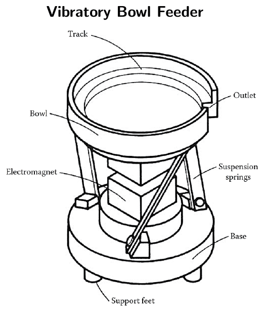
Figure 14.1: Vibratory bowl feeder: bowl, helical track, electromagnet, suspension springs and base.
An electromagnet in the base moves the bowl vertically. Leaf springs around the circumference couple this vertical motion with a torsional oscillation of the bowl. Together these draw parts from the centre of the bowl to the edge and then along a helical track up the side of the bowl to the outlet. (A video is linked in the original slides.)
14.2 Motion of a part on the track
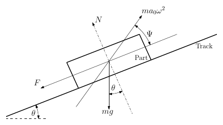
Figure 14.2: Part on an inclined, vibrating track.
| Symbol | Meaning |
|---|---|
| \(\theta\) | Angle of the track to the horizontal |
| \(\Psi\) | Vibration angle: the effective angle between the direction of track acceleration and the track |
| \(\omega\) | Angular vibration frequency |
| \(F\) | Friction force between part and track, parallel to the track |
| \(N\) | Normal reaction between part and track |
| \(a_0\) | Amplitude of vibration displacement |
| \(m\) | Mass |
Simplifying assumptions
- The part’s motion is independent of its shape.
- Air resistance is negligible.
- The part doesn’t roll down the track.
- Sliding up the track is most likely at maximum backward track acceleration, i.e. at the top of the cycle.
Forward sliding
At the top of the cycle the track has its maximum backward acceleration, \(a_0\omega^2\). Sliding happens when the force needed to accelerate the part parallel to the track exceeds the forces acting on it parallel to the track:
\[m a_0 \omega^2 \cos\Psi > mg\sin\theta + F \qquad F = \mu_s N = \mu_s (mg\cos\theta - m a_0\omega^2 \sin\Psi)\]
\[\boxed{\text{Forward sliding:}\quad \frac{a_0\omega^2}{g} > \frac{\mu_s\cos\theta + \sin\theta}{\cos\Psi + \mu_s\sin\Psi}}\]
Backward sliding
A similar analysis at the bottom of the cycle gives:
\[\text{Backward sliding:}\quad \frac{a_0\omega^2}{g} > \frac{\mu_s\cos\theta - \sin\theta}{\cos\Psi - \mu_s\sin\Psi}\]
Writing track acceleration and gravity normal to the track, \(A_n = a_0\omega^2\sin\Psi\) and \(g_n = g\cos\theta\):
\[\text{Forward:}\ \frac{A_n}{g_n} > \frac{\mu_s + \tan\theta}{\cot\Psi + \mu_s} \qquad \text{Backward:}\ \frac{A_n}{g_n} > \frac{\mu_s - \tan\theta}{\cot\Psi - \mu_s}\]
Hopping
Under some conditions the part leaves the track (hops): \(N = 0\), so \(F = 0\). The condition is
\[\frac{a_0\omega^2}{g} > \frac{\cos\theta}{\sin\Psi} \quad\text{or}\quad \frac{A_n}{g_n} > 1\]
Forward sliding outweighs backward sliding except at low values of \(\Psi\). Equating the two gives the cut-off: \[\tan\Psi = \frac{\tan\theta}{\mu_s}\]
Motion during a cycle can be complex, combining forward sliding, backward sliding and hopping. In general, feed rate increases when hopping is included.
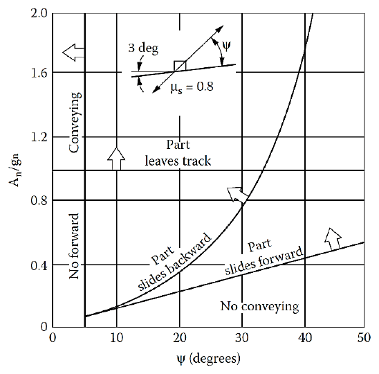
Figure 14.3: Conveying regions in the \(A_n/g_n\) vs \(\Psi\) plane for \(\theta = 3^\circ\) and \(\mu_s = 0.8\).
14.3 Factors affecting feed rate
- A) Frequency. Conveying velocity is inversely proportional to frequency, \(v \propto 1/\omega\), so lowering the drive frequency can raise the feed rate. A lower limit is set by vibrational coupling with assembly machinery attached to the feeder, and lower frequency needs a larger amplitude for the same acceleration.
- B) Track acceleration. Feed rate rises as \(A_n/g_n\) rises, until hopping becomes excessive and parts landing on the track behave erratically. Keep \(A_n/g_n > 1\), but below the level that causes excessive hopping.
- C) Vibration angle \(\Psi\). For given conditions there is an optimum vibration angle that maximises feed rate; it varies with friction.
- D) Track angle \(\theta\). Feed rate is usually highest at \(\theta = 0\). In practice \(\theta\) is 3–4° so parts can climb from the bottom of the bowl, but the feed rate is set by parts at the bottom (where the angle is zero) pushing parts along the track. So for calculations with a full bowl, assume \(\theta = 0\). When designing orientation devices, allow for this pushing, as it can cause jamming.
- E) Coefficient of friction. Increasing \(\mu_s\) increases feed rate. Typical values: steel on steel \(\mu_s = 0.2\); steel on rubber \(\mu_s = 0.8\). A rubber bowl lining also reduces noise and wear on parts.
14.4 Conveying velocity
The motion in the bowl combines vertical and horizontal movement. Vertical motion \(v\) is the same everywhere, while horizontal motion \(h\) depends on radius. The ratio of vertical to horizontal motion is the tangent of the vibration angle.
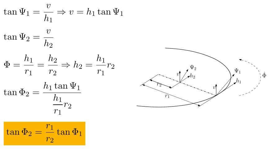
Figure 14.4: The vibration angle changes with radius because the horizontal displacement grows with radius.
\[\tan\Psi_1 = \frac{v}{h_1} \Rightarrow v = h_1\tan\Psi_1 \qquad \tan\Psi_2 = \frac{v}{h_2}\]
With angular displacement \(\Phi = h_1/r_1 = h_2/r_2\), so \(h_2 = (h_1/r_1)\,r_2\):
\[\tan\Psi_2 = \frac{r_1}{r_2}\tan\Psi_1\]
Worked problem
Leaf springs inclined at 60° to the horizontal are attached to the bowl at a radius of 100 mm. What is the vibration angle at the edge of a 300 mm diameter bowl?
- Vibration angle at 100 mm = 90° − 60° = 30°
- At 150 mm from the centre: \[\Psi = \arctan\left(\frac{100}{150}\tan 30^\circ\right) = 21^\circ\]
Conveying velocity depends mainly on \(\Psi\), \(a\) and \(\omega\):
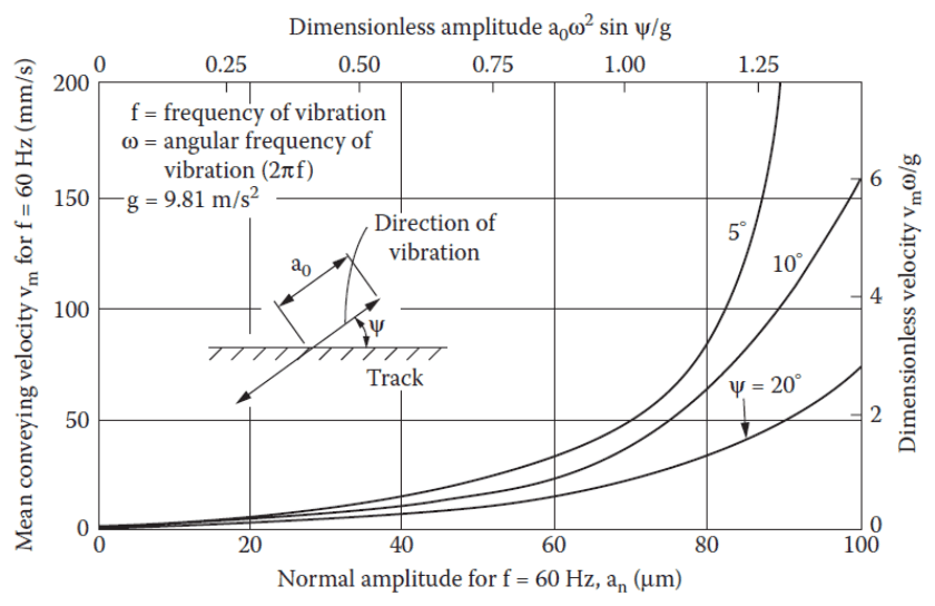
Figure 14.5: Mean conveying velocity vs normal amplitude, for several vibration angles.
Although parts appear to move at an almost constant speed, the motion is really a combination of many small, dissimilar motions that together look smooth. This combination is cyclic and usually repeats at the drive frequency.
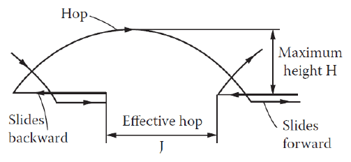
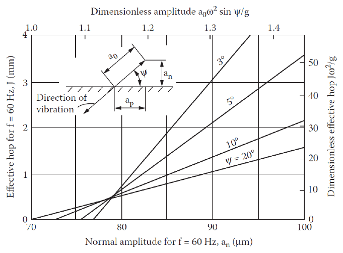
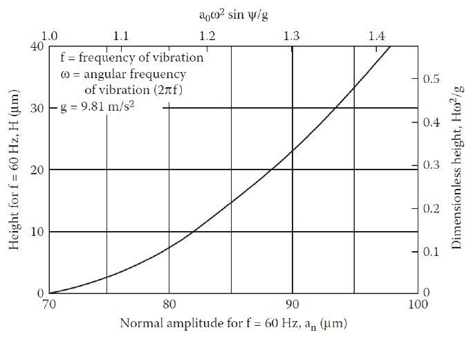
Figure 14.6: Typical motion during one cycle.
| Effective hop length | Maximum hop height |
|---|---|
 |
 |
14.5 Load sensitivity
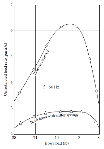
Figure 14.7: Feed rate varies with the load in the bowl.
Measures to combat load sensitivity:
- Regular bowl refills
- Overfeeding
- Varying vibration amplitude with load
- Increasing the spring stiffness of the bowl
Key points
- Forward sliding needs \(a_0\omega^2/g\) above a threshold set by \(\mu_s\), \(\theta\) and \(\Psi\); hopping needs \(A_n/g_n > 1\).
- Feed rate rises with lower frequency, higher (but not excessive) acceleration, an optimal \(\Psi\), low \(\theta\) and higher friction.
- Vibration angle varies with radius: \(\tan\Psi_2 = (r_1/r_2)\tan\Psi_1\).
Interactive applets
Each applet runs in the page; use Open full screen for more room, or open all of this chapter’s applets together.
Applet 14.1 · Part-on-track physics simulator
Set \(a_0\), \(f\), \(\Psi\), \(\theta\) and \(\mu_s\); a block on an oscillating track is animated, with a time plot of part vs track displacement colour-coded by phase (stick, slide forward, slide back, hop) and the mean conveying velocity.
Teaches: The sliding and hopping conditions, and why hopping increases feed rate. · Open full screen ↗
Applet 14.2 · Regime map explorer
An interactive version of Figure 14.3: hover over any (\(\Psi\), \(A_n/g_n\)) point to see the predicted regime, and drag sliders for \(\mu_s\) and \(\theta\) to see the boundaries move.
Teaches: How friction and track angle change the operating window. · Open full screen ↗
Applet 14.3 · Vibration angle vs radius calculator
Set the spring angle, spring radius and bowl diameter; the applet draws a top-down bowl colour-mapped by \(\Psi\).
Teaches: The worked problem and radius dependence. · Open full screen ↗
Applet 14.4 · Feed-rate tuning game
Adjust frequency and amplitude to hit a target feed rate without excessive hopping or jamming, while the bowl empties (load sensitivity).
Teaches: Practical tuning trade-offs. · Open full screen ↗