Lecture 6: Servo Systems
Servo Systems
A servo system, with respect to DC motors, describes how the motor output is controlled to give a defined output. This output could be speed, position or torque (as inferred from the current draw).
The simplest arrangement is a DC motor supplied directly by a voltage, with speed, position and torque (\(i\)) as its outputs.
Open loop

- Servo systems typically form part of a larger electromechanical system, so the motors are usually digitally controlled by programmable logic controllers (PLCs), microcontrollers or microprocessors.
- Additional driver circuitry is often needed for high-current switching, because the controller cannot supply the motor current itself.
- Some motor manufacturers provide the controller and driver as a single electronic board, making it easier to interface with a particular motor. The input signal depends on the manufacturer of the board, but it tells the motor what output (speed, position etc.) is required.
This is an open-loop system: nothing checks whether the motor actually achieves the requested output.
Closed loop
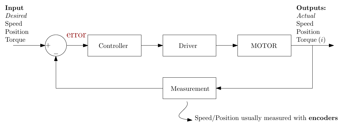
To complete the servo system, feedback is used:
- The actual motor output is measured (speed and position are usually measured with encoders).
- It is compared with the desired output to give an error:
\[ e = \text{desired output} - \text{measured output} \]
- If there is a mismatch, the controller acts on the driver to change the motor’s output.
This is a closed-loop system. Higher-end motor manufacturers provide dedicated motor controllers, again combining controller and driver in one unit, that receive the measurement signals directly and adjust the drive to achieve the required motor output.
Controllers
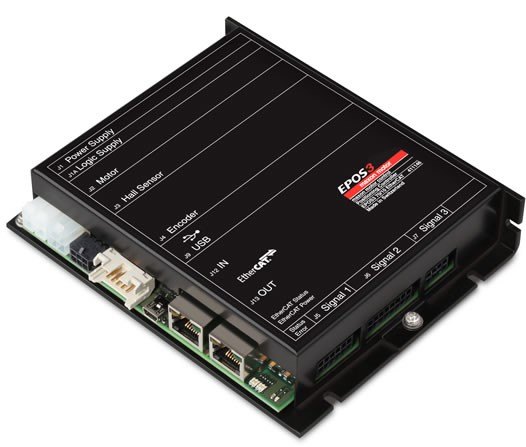
Positioning controller from Maxon motors (also capable of speed and torque control).
Control basics:
- There are many alternative strategies for turning the error signal into the required driver signal.
- Among the simplest is proportional (P) control.
- Among the most common is proportional plus integral plus derivative (PID) control.
- Control strategies are an ongoing area of research.
Encoders
Key to a servo system is feedback of the measured output. To measure motor speed and/or position, devices called encoders are routinely used. There are two main types.
| Absolute encoders | Incremental encoders |
|---|---|
| Unique code for every angular position | Generate an output signal when the shaft moves through a defined angle |
| Only need to consume power when taking a reading | Need to be powered at all times during operation |
| Typically more expensive than incremental encoders | Less expensive and less complex than absolute encoders |
| Do not lose position information when power is removed | Each time power is lost, the position is lost or an initialisation step is required |
Absolute encoders
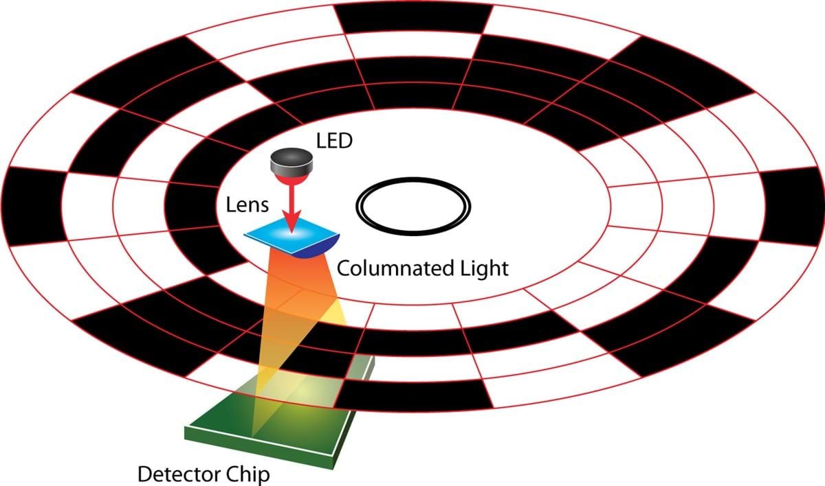
- An optical encoder is based on varying light transmission through a disk.
- In an absolute encoder, each bit sequence (pattern) represents a defined position on the disk, and so a defined position of the rotor. In the figure the current code reads 1001.
- For absolute encoders it is typical for the count to change using what is known as Gray code.
Task: Research “Gray code” and find out why it is preferred over plain binary code.
Incremental encoders
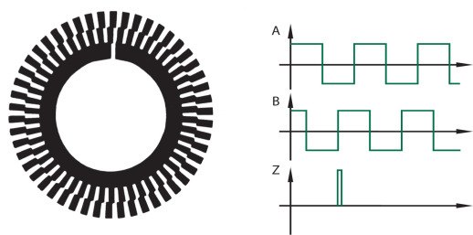
- In an incremental optical encoder it is the changes in the bit sequence that give information about the position of the rotor.
- The incremental encoder can determine position relative to the start point, but the start point typically resets to zero on shutdown.
- Some incremental optical encoders include an index channel (Z) that helps to determine absolute position: it produces one pulse per revolution.
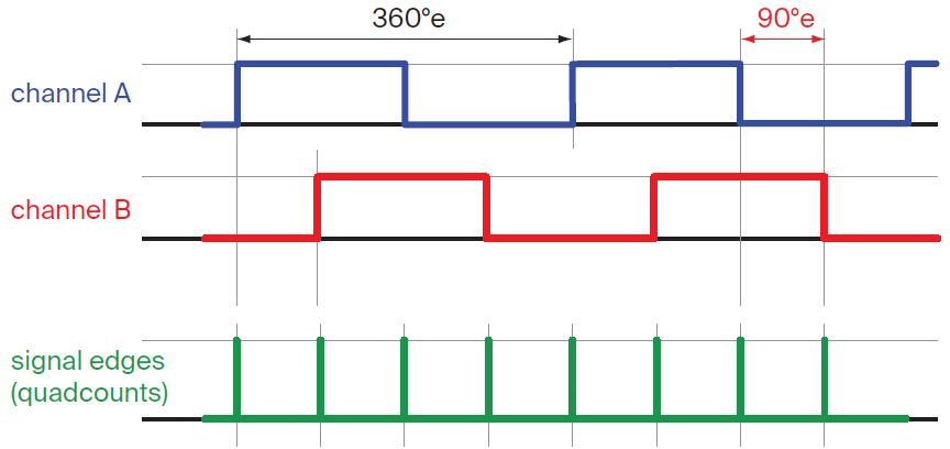
- Two-channel incremental encoders are typically set up in quadrature: channel A is 90° out of phase with channel B. Which channel leads tells you the direction of rotation.
- For high-resolution applications, quadcounts (every rising and falling edge of both channels, four per cycle) can be used to determine position.
Additional information
- With all encoder types, additional circuitry is required to interpret the signals. These circuits can also measure the time between encoder pulses.
- Measuring the change in angular position and the time taken for that change gives a measure of rotor speed:
\[ \omega \approx \frac{\Delta \theta}{\Delta t} \]
- Typical optical encoders have 256 to 2048 counts per revolution, a resolution of
\[ \frac{360^\circ}{256} \approx 1.4^\circ \quad \text{to} \quad \frac{360^\circ}{2048} \approx 0.18^\circ \]
- Although optical encoders are the most common, other types include magnetic, mechanical and induction encoders.
Case Study: Designing an Electromechanical System
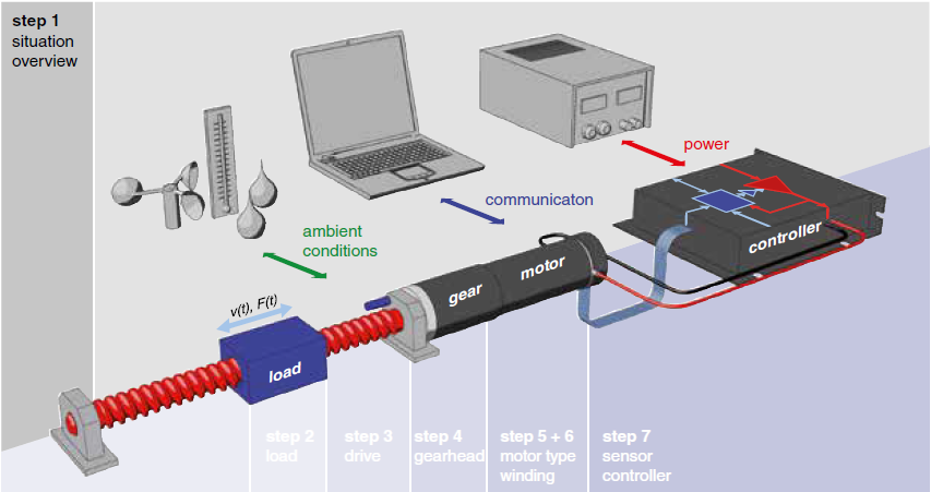
The main focus so far has been on DC motor types, with some emphasis on how they are controlled. It is important to remember that motors are employed to do mechanical work, and so form part of a larger system. When designing these systems there are considerations other than just the motor.
One approach to electromechanical system design:
- Overview: Define the basic layout. What are the ambient conditions? Are there any size restrictions?
- Load requirement: What operating times are expected? How high are the forces and torques?
- Mechanical drive: Type of drive (belt, chain, linear screw etc.) and bearing types.
- Gearhead: Are gears required? What type of lubrication? How much backlash is permissible?
- Motor selection: Torque and speed requirements influence the motor type. The service life of the motor can also play a role.
- Controller type: What feedback sensor should be used? Is it compatible with the controller options? What control strategy should be employed?
Worked Example: Sizing a Motor for a Flywheel
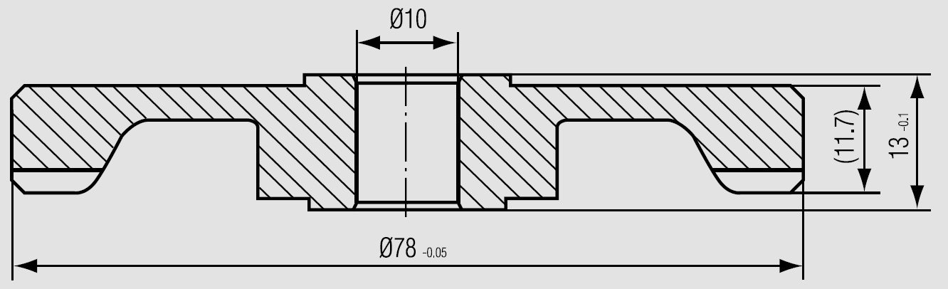
An aluminium flywheel (diameter 78 mm, mass approx. 300 g) is to be accelerated to 17 000 rpm in a maximum of 7 seconds. The available voltage is 24 V. The exact dimensions of the flywheel are shown below. Determine a suitable motor.
Solution
To find the torque required, use
\[ T_m = J\,\alpha \]
To simplify, assume the mass of the flywheel is distributed uniformly (a solid disc). The moment of inertia is then
\[ J = \frac{1}{2}\,m\,r^2 = \frac{1}{2} \times 0.3 \times 0.039^2 = 0.23 \times 10^{-3}\,\text{kg·m}^2 \]
The torque required for constant acceleration is
\[ T_m = J\,\alpha = J \cdot \frac{\pi}{30}\cdot\frac{\Delta n}{\Delta t} = 0.23 \times 10^{-3} \times \frac{\pi}{30} \times \frac{17\,000}{7} = 0.058\,\text{N·m} \]
where \(\frac{\pi}{30}\) converts a speed in rpm to rad/s.
We therefore look for a motor with a maximum speed above 17 000 rpm that can deliver approximately 60 mN·m of torque for 7 seconds. The nominal (continuous) torque can be much less than this, because the high torque is only needed during the acceleration. An ECX SPEED 22 L High Power motor should suffice.
Interactive Elements
Each element below runs in the page; use Open full screen for more room.
Closed-loop servo simulator
Reuse the Lecture 3 motor model and close the loop around it: set a target speed or position, choose P, PI or PID control and adjust the gains, and watch the response (overshoot, steady-state error, settling time) against the open-loop response. This makes the difference between open and closed loop, and the effect of each PID term, visible.
Quadrature encoder
Spin an encoder disk either way and see channels A, B and the index Z drawn live, with the quadcount, the direction (which channel leads) and the speed from \(\Delta\theta/\Delta t\). A slider sets the number of slots (8 to 64, so they stay visible), and the resolution of real 256 to 2048-count encoders is given alongside.
Gray code versus binary
An absolute encoder disk in plain binary and in Gray code side by side. As the disk turns, a small misalignment between the read heads makes the binary reading jump to wrong values at transitions (for example 0111 → 1000), while Gray code changes only one bit at a time. This answers the lecture’s Gray code task.
Flywheel motor sizing calculator
Enter the flywheel dimensions, target speed and acceleration time to get \(J\), the required torque and the power, and compare them with candidate motors’ data sheet values.
Knowledge Check
Q1. What distinguishes a closed-loop servo system from an open-loop one?
- It uses a driver for high-current switching
- It measures the actual output and feeds it back to compare with the desired output
- It uses a PLC instead of a microcontroller
- The controller and driver are on a single board
Answer
B. Feedback of the measured output, compared with the desired output to give an error, is what makes the system closed loop. Drivers and single-board controllers appear in both open- and closed-loop systems.
Q2. Why is a separate driver usually needed between a microcontroller and a DC motor?
Answer
The microcontroller’s outputs can only supply small currents (typically tens of milliamps), while the motor needs much larger currents. The driver does the high-current switching.
Q3. Give one advantage of an absolute encoder over an incremental encoder, and one advantage of an incremental encoder over an absolute one.
Answer
Absolute: it does not lose its position when power is removed (and only needs power when taking a reading). Incremental: it is cheaper and less complex.
Q4. In a two-channel quadrature encoder, channels A and B are 90° out of phase. What does this allow the encoder circuitry to determine?
- The absolute position of the shaft
- The direction of rotation
- The motor torque
- The supply voltage
Answer
B. Whether A leads B or B leads A tells you which way the shaft is turning. The edges of both channels (quadcounts) also give four times the resolution of one channel.
Q5. What is the purpose of the index channel (Z) on some incremental encoders?
Answer
It produces one pulse per revolution, giving a fixed reference point that helps to determine position, for example when the system is initialised after power-up.
Q6. An optical encoder has 1024 counts per revolution. What is its angular resolution? If it is read in quadrature (quadcounts), what is the resolution then?
Answer
\(360^\circ/1024 \approx 0.35^\circ\). With quadcounts there are \(4 \times 1024 = 4096\) counts per revolution, so the resolution is \(360^\circ/4096 \approx 0.088^\circ\).
Q7. Why is Gray code preferred over plain binary code on absolute encoders?
Answer
In Gray code only one bit changes between adjacent positions. In plain binary several bits can change at once (for example 0111 → 1000); if the read heads are slightly misaligned, they do not all switch at exactly the same moment and the encoder can briefly read a completely wrong position. With Gray code the worst case is a reading that is one step out.
Q8. How can an encoder be used to measure speed as well as position?
Answer
The interface circuitry measures the change in angular position and the time taken for that change: \(\omega \approx \Delta\theta/\Delta t\) (or equivalently it measures the time between encoder pulses).
Q9. In the flywheel example, what would the required torque be if the same flywheel had to reach 17 000 rpm in 3.5 s instead of 7 s?
Answer
Torque is proportional to the acceleration, \(T_m = J\alpha\), and halving the time doubles the acceleration, so the torque doubles to about 0.12 N·m (117 mN·m).
Q10. List the six steps of the electromechanical system design approach given in the lecture.
Answer
- Overview (layout, ambient conditions, size restrictions); 2. Load requirement (operating times, forces and torques); 3. Mechanical drive (belt, chain, screw; bearings); 4. Gearhead (gears, lubrication, backlash); 5. Motor selection (torque, speed, service life); 6. Controller type (feedback sensor, compatibility, control strategy).