Microcontrollers Part 1 — Arduino fundamentals, LEDs and digital output
Learning outcomes
By the end of this part you should be able to:
- Describe the architecture of the Arduino Uno R3 and the electrical limits of its I/O pins
- Size a current-limiting resistor for an LED, including standard values and power rating
- Configure the toolchain and explain how a sketch is compiled and executed
- Drive digital outputs using appropriate data types, named constants and functions
- Distinguish blocking (
delay) from non-blocking (millis) timing and know when each is appropriate
1. Prototyping on a breadboard
A solderless breadboard is a matrix of spring-contact clips:
- Terminal strips: each half-column of five holes (a–e, f–j) is one clip. The centre channel isolates the two halves, so a DIP IC can straddle it.
- Power rails: continuous along the board’s length (on some full-size boards they are split at the midpoint). Top and bottom rails are independent.
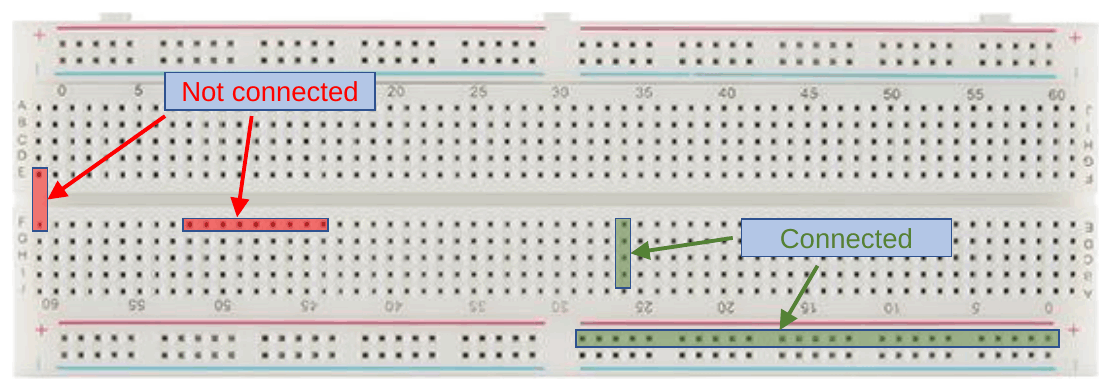
Practical limits worth knowing: contact resistance is typically 10–50 mΩ per contact, the clips are rated at roughly 1 A, and adjacent strips have a few pF of stray capacitance. That is irrelevant for LEDs and sensors, but it rules breadboards out for motor currents and high-frequency signals. Move power circuits to screw terminals or a soldered board.
Try it: Breadboard continuity lab — add wires and components, reveal the hidden strips, test continuity between any two holes, and check whether each component is placed correctly. · Open full screen ↗
2. LEDs and current limiting
2.1 Polarity
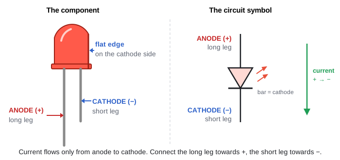
The anode (+, long leg) must be at the higher potential; the cathode (−, short leg, flat edge on the lens) at the lower. Reverse-biased, an LED does not conduct, and most are only rated to about 5 V reverse.
2.2 Why an LED cannot be connected directly to a supply
An LED is a p–n junction diode. Its forward current follows the Shockley diode equation:
\[I_D = I_S\left(e^{V_D / nV_T} - 1\right)\]
where \(I_S\) is the saturation current (pA–nA), \(n\) the ideality factor (≈ 1–2) and \(V_T = kT/q \approx 26\ \text{mV}\) at room temperature. Because current rises exponentially with voltage, a change of only a few tens of millivolts across the junction changes the current several-fold. The LED therefore cannot set its own operating point. Connected directly to a 9 V battery, the current is limited only by the battery’s internal resistance, and the junction overheats and fails within seconds.
A series resistor gives a linear element that sets the current. Above the knee of the curve the LED voltage is roughly constant at its forward voltage \(V_f\), so:
\[I = \frac{V_s - V_f}{R} \qquad\Rightarrow\qquad R = \frac{V_s - V_f}{I_F}\]
2.3 Choosing the resistor: LED circuit explorer
Use the interactive LED circuit explorer to see how the resistor sets the current. Choose a supply voltage and an LED colour (which sets the forward voltage \(V_f\)), then slide through the standard E12 resistor values. The circuit shows charge flowing and the LED glowing, a meter shows the current against the LED’s 20 mA rating and 30 mA maximum, and the calculation updates with every change. Pick a resistor that is too small and the LED burns out.
Open the LED circuit explorer · Open full screen ↗
Try these:
- With the 9 V battery and a red LED, find the smallest standard resistor that keeps the current at or below 20 mA.
- Step down one value, then another. What does the meter show, and what is the message?
- Slide all the way to no resistor. What happens, and why?
- Switch to a blue LED. Why does the smallest safe resistor change?
- Try the 3.3 V supply with a white LED. Why is this a poor combination?
- At the resistor you found in task 1, how much power does the resistor dissipate? Is a standard ¼ W resistor enough?
Answers
- 390 Ω. Exactly 20 mA needs \(R = (9 - 2.0)/0.020 = 350\ \Omega\), which is not a standard value. The next E12 value up is 390 Ω, giving \((9 - 2.0)/390 = 17.9\ \text{mA}\). Even if the resistor is 5 % low (370 Ω), the current is 18.9 mA, still within the rating.
- 330 Ω gives 21.2 mA and 270 Ω gives 25.9 mA: both are over the 20 mA rating (amber). The LED still lights but runs hot and wears out sooner. That is why you always round the calculated value up.
- With no resistor, only the battery’s small internal resistance limits the current, so it tries to reach amps. That is far past the 30 mA maximum, and the LED burns out and then conducts nothing.
- A blue LED has a higher forward voltage (3.2 V), so the resistor has less voltage across it: \((9 - 3.2)/0.020 = 290\ \Omega\), so the smallest safe standard value is 330 Ω.
- Only \(3.3 - 3.2 = 0.1\ \text{V}\) is left across the resistor. The current then depends heavily on the exact forward voltage, which varies from LED to LED, so the brightness is unpredictable. Use the 5 V supply instead.
- \(P = I^2R = 0.0179^2 \times 390 \approx 125\ \text{mW}\): half of a ¼ W (250 mW) rating. That is acceptable with the common 50 % derating, but use a ½ W resistor in a warm enclosure.
2.4 Driving an LED from an Arduino pin
From a 5 V output pin, with a red LED at 15 mA: \(R = (5 - 2)/0.015 = 200\ \Omega\) → use 220 Ω. In practice the pin’s output voltage drops under load (the ATmega328P datasheet gives \(V_{OH} \approx 4.2\ \text{V}\) at 20 mA), so the actual current is a little lower than calculated. That is another reason not to design right at the limit.
3. The microcontroller in a mechatronic system
A microcontroller (MCU) is the decision-making element of an embedded control system. It samples sensors, executes a control law in firmware, and commands actuators, usually through driver stages, because MCU pins can source only milliamps.
| Inputs (sensors) | Typical interface | Outputs (actuators/displays) | Typical interface |
|---|---|---|---|
| Temperature (thermistor, LM35) | Analogue voltage → ADC | LEDs | Digital output / PWM |
| Humidity (DHT22) | Single-wire digital | Stepper motors | Step/direction to a driver (A4988) |
| Light (LDR, photodiode) | Analogue via divider | DC motors | PWM to an H-bridge (L298N) |
| Infrared (PIR, IR receiver) | Digital | Servos | 50 Hz PWM pulse width |
| Distance (HC-SR04 ultrasonic) | Digital pulse timing | LCD displays | I²C or parallel |
| Buzzers | Digital output / tone() |
In the design project the MCU will monitor the voltage of a renewable energy source and switch the load to a battery when that voltage falls (Parts 5–8).
4. Arduino Uno R3 hardware
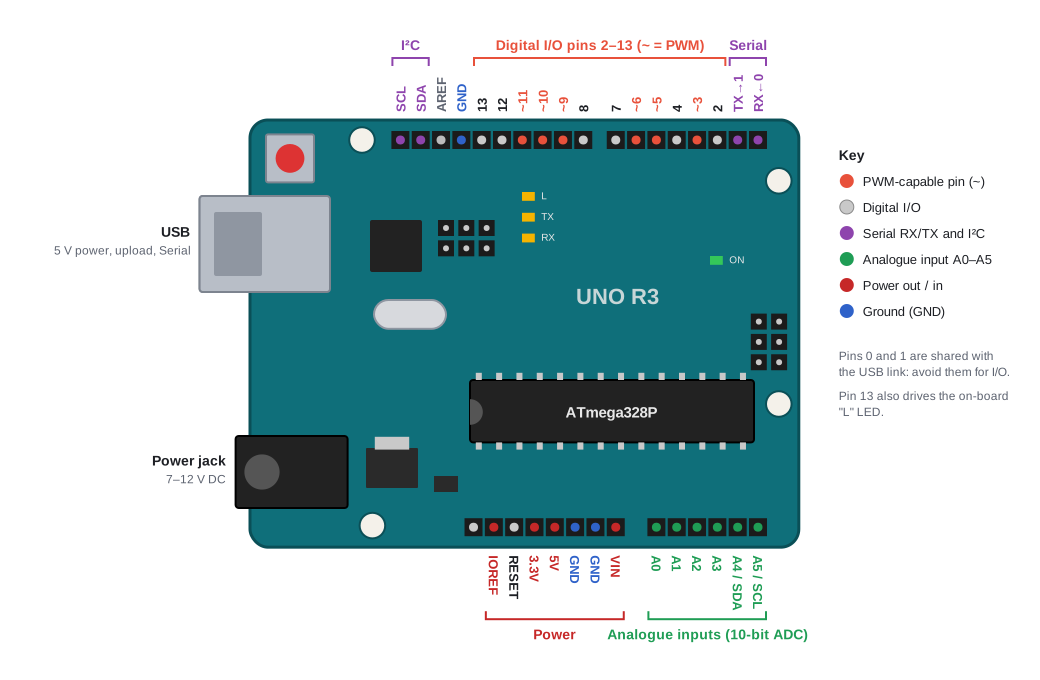
The Uno R3 (the Elegoo board in the lab is a compatible clone) is built around the Microchip ATmega328P:
| Parameter | Value |
|---|---|
| Core | 8-bit AVR RISC, 16 MHz (≈ 16 MIPS) |
| Flash (program) / SRAM (variables) / EEPROM | 32 KB (0.5 KB used by the bootloader) / 2 KB / 1 KB |
| Digital I/O | 14 pins (D0–D13), 6 with PWM (~ 3, 5, 6, 9, 10, 11) |
| Analogue inputs | 6 (A0–A5), 10-bit ADC (0–1023) |
| Logic level | 5 V |
| Pin current | 20 mA recommended, 40 mA absolute maximum per pin; 200 mA total through VCC/GND |
| Supply input | USB 5 V, or 7–12 V on the barrel jack / Vin |
| Serial interfaces | UART (D0 RX / D1 TX, shared with USB), SPI (D10–D13 / ICSP), I²C (A4 SDA / A5 SCL) |
| Feature | Function |
|---|---|
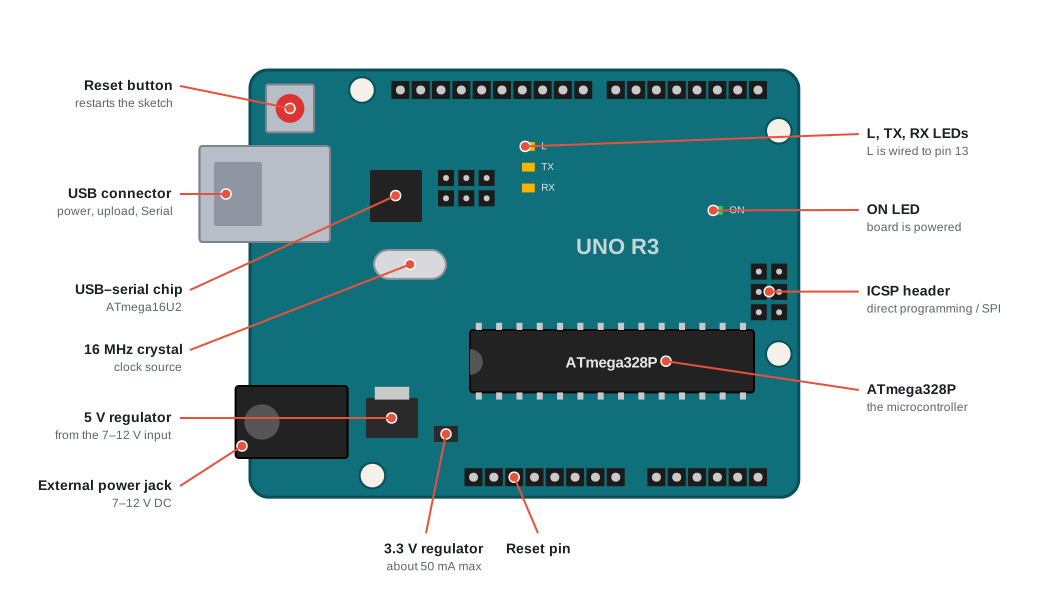
| USB connector (with a USB–serial converter) | Powers the board, uploads firmware via the bootloader, carries Serial data |
| External power jack / Vin | 7–12 V input to the on-board 5 V linear regulator. Above ~12 V the regulator dissipates excessive heat: \(P = (V_{in} - 5)\,I\) |
| 3.3 V regulator | Low-current (≈ 50 mA) 3.3 V output for 3.3 V sensors |
| 16 MHz crystal | Clock source; sets timing accuracy for millis(), serial baud rates and PWM |
| Reset button / pin | Restarts the program from setup() |
| ICSP header | Direct programming of the ATmega328P (bypassing the bootloader) and SPI access |
| D0/D1 (RX/TX) | Used by Serial and for uploading; avoid using them as general I/O |
5. Toolchain and program structure
Install the Arduino IDE 2.x from https://www.arduino.cc/en/software.
Select the board: Tools › Board › Arduino AVR Boards › Arduino Uno.
Select the serial port: Tools › Port (COMx on Windows,
/dev/ttyACM0or/dev/cu.usbmodem…on Linux/macOS).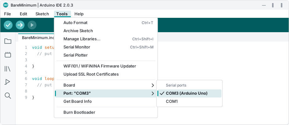
Selecting the serial port in the Tools menu Start from File › Examples › 01.Basics › BareMinimum.
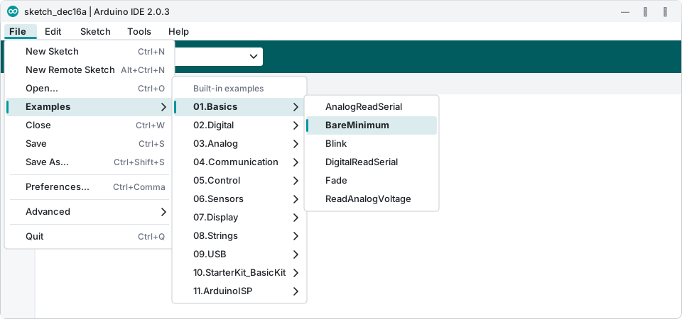
File › Examples › 01.Basics › BareMinimum
Verify compiles the sketch (C++ with the Arduino core library, using avr-gcc); Upload compiles and transfers the program to the board through the bootloader. Every Arduino sketch has the same two functions, as in the BareMinimum example:
void setup() {
  // put your setup code here, to run once:

}

void loop() {
  // put your main code here, to run repeatedly:

}setup()runs once, when the board powers up or is reset. Use it to configure pins (pinMode) and start serial communication (Serial.begin).loop()then runs over and over, forever, until the power is removed.
There is no operating system: loop() is a super-loop, and anything that blocks inside it (a long delay(), waiting on a sensor) stops every other task. Section 9 returns to this point.
6. Digital output
pinMode(pin, OUTPUT) configures a pin’s data-direction register; digitalWrite(pin, HIGH) drives it to ≈ 5 V (sourcing current) and LOW to ≈ 0 V (sinking current). An LED can be wired either way:
| Configuration | Wiring | LED on when |
|---|---|---|
| Source (active-HIGH) | Pin → resistor → LED anode, cathode → GND | HIGH |
| Sink (active-LOW) | 5 V → resistor → LED anode, cathode → pin | LOW |
Example 1a — blink an LED
/*
 * Example 1a: Blink an LED at 1 Hz (0.5 s on, 0.5 s off).
 * Hardware: red LED + 220 Ω resistor from D13 to GND.
 */

const uint8_t  kLedPin       = 13;    // the LED is wired to digital pin 13
const uint16_t kHalfPeriodMs = 500;   // on time = off time, in milliseconds

// setup() runs once, when the board powers up or is reset.
void setup() {
  pinMode(kLedPin, OUTPUT);           // pin 13 drives (outputs to) the LED
}

// loop() runs over and over, forever.
void loop() {
  digitalWrite(kLedPin, HIGH);        // 5 V on pin 13: LED on
  delay(kHalfPeriodMs);               // wait 500 ms
  digitalWrite(kLedPin, LOW);         // 0 V on pin 13: LED off
  delay(kHalfPeriodMs);               // wait 500 ms, then loop() starts again
}
Run it: Example 1a in the code runner — the active line is highlighted as the LED blinks. · Open full screen ↗
Why const uint8_t and not just int?
constmeans the value can never change while the program runs. The LED is always on pin 13, so we lock that in. If you accidentally writekLedPin = 12;later in the code, the compiler stops with an error instead of letting the mistake through.uint8_tis a whole number that uses 1 byte of memory and holds 0 to 255. Pin numbers on the Uno only go up to 19, so 1 byte is plenty. Anintuses 2 bytes. The Uno only has 2 KB of memory for variables, so it’s a good habit to use the smallest type that fits.uint16_tis the same idea for the delay: 2 bytes, 0 to 65 535, which covers delays up to about 65 seconds.
Why the k at the start of the names?
It’s a naming convention: k stands for constant. When you see kLedPin anywhere in the code, you know straight away it’s a fixed value set at the top of the file, not a variable that changes as the program runs. Ordinary variables, such as ledOn in Section 9, have no k.
Pin 13 also drives the on-board “L” LED, which is a useful sanity check before any external wiring.
7. Data types and named constants
On an 8-bit AVR, type sizes differ from a desktop PC, and with only 2 KB of SRAM they matter:
| Type | Size | Range | Typical use |
|---|---|---|---|
bool |
1 byte | true / false |
Flags and states |
uint8_t |
1 byte | 0–255 | Pin numbers, PWM duty, small counters |
int / int16_t |
2 bytes | −32 768 to 32 767 | General integers, analogRead() results |
uint16_t |
2 bytes | 0–65 535 | Short delays in ms |
long / int32_t |
4 bytes | ±2.1 × 10⁹ | Large counts |
unsigned long |
4 bytes | 0–4.29 × 10⁹ | Timestamps from millis() |
float |
4 bytes | ~7 significant digits | Measured voltages, scaled values (double is the same as float on AVR) |
String |
heap | text | Use sparingly — see note |
Good practice:
- Declare fixed values as
const. This documents intent, lets the compiler substitute the value directly instead of using SRAM, and makes a hardware change (e.g. moving an LED to another pin) a one-line edit. - Use the smallest type that fits the range, and
unsigned longfor anything compared withmillis(). - Avoid the Arduino
Stringclass in long-running firmware: repeated concatenation fragments the 2 KB heap and can eventually crash the program. Use string literals,chararrays, or theF()macro, which keeps literal text in flash:Serial.println(F("Source: RES"));.
const uint8_t kVoltageInPin = A0;      // analogue input
float         sourceVoltage = 0.0f;    // measured value, updated at run time
const char    kSourceName[] = "RES";   // fixed text, no heap allocation
8. Sequencing outputs: loops, arrays and functions
Example 1b — varying the on-time from 0.1 s to 1 s
Repeating the same four lines for each delay is error-prone. Store the parameters in an array and iterate:
/*
 * Example 1b: Blink an LED with on-times stepping from 0.1 s to 1 s.
 * Hardware: red LED + 220 Ω resistor from D13 to GND.
 */

const uint8_t  kLedPin      = 13;                          // LED pin
const uint16_t kOffMs       = 500;                         // off time after each blink (ms)
const uint16_t kOnTimesMs[] = {100, 250, 500, 750, 1000};  // on time for each blink (ms)

// Number of values in the array = total bytes / bytes per value = 5.
// If you add a value to kOnTimesMs, this updates automatically.
const size_t   kNumSteps    = sizeof(kOnTimesMs) / sizeof(kOnTimesMs[0]);

void setup() {
  pinMode(kLedPin, OUTPUT);              // LED pin is an output
}

void loop() {
  // i takes the values 0, 1, 2, 3, 4: one pass for each value in the array.
  for (size_t i = 0; i < kNumSteps; ++i) {
    digitalWrite(kLedPin, HIGH);         // LED on
    delay(kOnTimesMs[i]);                // stay on for the i-th on time
    digitalWrite(kLedPin, LOW);          // LED off
    delay(kOffMs);                       // stay off for 500 ms
  }
}
Run it: Example 1b in the code runner — watch i step through the array and the on-time grow. · Open full screen ↗
How kNumSteps is worked out
const size_t kNumSteps = sizeof(kOnTimesMs) / sizeof(kOnTimesMs[0]);The for loop needs to know how many on-times are in the array, so that it stops after the last one. This line counts them for you.
What sizeof does. sizeof(something) gives the amount of memory that something takes up, in bytes. It is worked out by the compiler when you press Verify or Upload, so it costs nothing while the program runs.
Step by step:
kOnTimesMsholds 5 values, and each one is auint16_t, which takes 2 bytes. Sosizeof(kOnTimesMs)= 5 × 2 = 10 bytes (the whole array).kOnTimesMs[0]is just the first value in the array, oneuint16_t. Sosizeof(kOnTimesMs[0])= 2 bytes (one value).- Divide the whole by one: 10 ÷ 2 = 5 values. So
kNumSteps= 5.
| Part of the line | Means | Value |
|---|---|---|
sizeof(kOnTimesMs) |
bytes used by the whole array | 10 |
sizeof(kOnTimesMs[0]) |
bytes used by one value | 2 |
kNumSteps |
number of values in the array | 10 ÷ 2 = 5 |
Why not just write 5? You could, but then if you add a sixth on-time, say {100, 250, 500, 750, 1000, 1500}, you must also remember to change the 5 to 6. Forget, and the loop never uses the new value. With the sizeof version the count updates by itself: 12 ÷ 2 = 6. This is also why the array can be declared with empty brackets, kOnTimesMs[]: the compiler counts the values in the { } list itself.
Why size_t? size_t is the standard type for sizes and counts. It can never be negative, and it is the type that sizeof gives back, so it is the natural choice for kNumSteps and for the loop counter i that is compared with it.
Exercise 1c — three LEDs in sequence
Task: blink a red LED 2 times, then a green LED 3 times, then a blue LED 4 times, each blink 0.5 s on and 0.5 s off, and repeat. Use only digitalWrite() and delay() in loop().
Every blink is written out as four lines: LED on, wait, LED off, wait. Nine blinks therefore need 36 lines.
/*
 * Exercise 1c: Blink three LEDs in sequence: red 2 times, green 3 times,
 * blue 4 times, each blink 0.5 s on and 0.5 s off. Then repeat.
 * Written out in full using only digitalWrite() and delay() in loop().
 * Hardware: each LED in series with a 220 Ω resistor to GND.
 */

const uint8_t  kRedPin       = 13;     // red LED pin
const uint8_t  kGreenPin     = 12;     // green LED pin
const uint8_t  kBluePin      = 11;     // blue LED pin
const uint16_t kHalfPeriodMs = 500;    // on time and off time (ms)

void setup() {
  pinMode(kRedPin, OUTPUT);            // all three LED pins are outputs
  pinMode(kGreenPin, OUTPUT);
  pinMode(kBluePin, OUTPUT);
}

void loop() {
  // Red: blink 1 of 2
  digitalWrite(kRedPin, HIGH);         // red on
  delay(kHalfPeriodMs);                // wait 0.5 s
  digitalWrite(kRedPin, LOW);          // red off
  delay(kHalfPeriodMs);                // wait 0.5 s

  // Red: blink 2 of 2
  digitalWrite(kRedPin, HIGH);         // red on
  delay(kHalfPeriodMs);                // wait 0.5 s
  digitalWrite(kRedPin, LOW);          // red off
  delay(kHalfPeriodMs);                // wait 0.5 s

  // Green: blink 1 of 3
  digitalWrite(kGreenPin, HIGH);       // green on
  delay(kHalfPeriodMs);                // wait 0.5 s
  digitalWrite(kGreenPin, LOW);        // green off
  delay(kHalfPeriodMs);                // wait 0.5 s

  // Green: blink 2 of 3
  digitalWrite(kGreenPin, HIGH);       // green on
  delay(kHalfPeriodMs);                // wait 0.5 s
  digitalWrite(kGreenPin, LOW);        // green off
  delay(kHalfPeriodMs);                // wait 0.5 s

  // Green: blink 3 of 3
  digitalWrite(kGreenPin, HIGH);       // green on
  delay(kHalfPeriodMs);                // wait 0.5 s
  digitalWrite(kGreenPin, LOW);        // green off
  delay(kHalfPeriodMs);                // wait 0.5 s

  // Blue: blink 1 of 4
  digitalWrite(kBluePin, HIGH);        // blue on
  delay(kHalfPeriodMs);                // wait 0.5 s
  digitalWrite(kBluePin, LOW);         // blue off
  delay(kHalfPeriodMs);                // wait 0.5 s

  // Blue: blink 2 of 4
  digitalWrite(kBluePin, HIGH);        // blue on
  delay(kHalfPeriodMs);                // wait 0.5 s
  digitalWrite(kBluePin, LOW);         // blue off
  delay(kHalfPeriodMs);                // wait 0.5 s

  // Blue: blink 3 of 4
  digitalWrite(kBluePin, HIGH);        // blue on
  delay(kHalfPeriodMs);                // wait 0.5 s
  digitalWrite(kBluePin, LOW);         // blue off
  delay(kHalfPeriodMs);                // wait 0.5 s

  // Blue: blink 4 of 4
  digitalWrite(kBluePin, HIGH);        // blue on
  delay(kHalfPeriodMs);                // wait 0.5 s
  digitalWrite(kBluePin, LOW);         // blue off
  delay(kHalfPeriodMs);                // wait 0.5 s
}
Run it: Exercise 1c in the code runner — step down the long list of digitalWrite and delay calls. · Open full screen ↗
This works, and every step is easy to see, but it is long and repetitive. Changing one LED’s count means adding or deleting lines in exactly the right place. Exercise 1c(2) produces the same sequence with far less code.
Exercise 1c(2) — the same sequence with a struct, a table and a function
Task: produce exactly the same sequence as Exercise 1c, but without writing every blink out.
The sketch below uses three tools that keep the code short and easy to change:
- a
struct(BlinkStep) that bundles the two facts about each stage of the sequence: which pin, and how many blinks; - a table (
kSequence) listing the stages in order. Changing the order, a count or a pin means editing one line of this table; - a function (
blink) that blinks any LED any number of times, so the on/off code is written once and reused for all three LEDs.
loop() then reads the table one row at a time and calls blink() with that row’s pin and count. Each blink is also reported on the Serial Monitor.
/*
 * Exercise 1c(2): the same sequence as Exercise 1c (red 2 times, green 3 times,
 * blue 4 times, each blink 0.5 s on and 0.5 s off), using a struct, a table
 * and a function instead of writing every step out.
 * Hardware: each LED in series with a 220 Ω resistor to GND.
 */

// ---- Pin and timing constants ----
const uint8_t       kRedPin       = 13;    // red LED on digital pin 13
const uint8_t       kGreenPin     = 12;    // green LED on digital pin 12
const uint8_t       kBluePin      = 11;    // blue LED on digital pin 11
const uint16_t      kHalfPeriodMs = 500;   // time on, and time off, for each blink (ms)
const unsigned long kBaudRate     = 9600;  // Serial Monitor speed (bits per second)

// ---- A struct groups related values into one new type ----
// Each BlinkStep describes one stage of the sequence:
// which pin to blink, and how many times to blink it.
struct BlinkStep {
  uint8_t pin;     // the LED's pin number
  uint8_t count;   // how many blinks for this LED
};

// ---- The sequence, as a table (an array of BlinkStep) ----
// Each row is one BlinkStep written as {pin, count}.
// To change the order, a pin or a count, edit this table only.
const BlinkStep kSequence[] = {
  {kRedPin,   2},  // row 0: red blinks 2 times
  {kGreenPin, 3},  // row 1: green blinks 3 times
  {kBluePin,  4},  // row 2: blue blinks 4 times
};

// ---- Blink one LED 'count' times and report each blink ----
// pin          - the pin the LED is connected to
// count        - number of blinks
// halfPeriodMs - on time (and off time) in milliseconds
void blink(uint8_t pin, uint8_t count, uint16_t halfPeriodMs) {
  for (uint8_t i = 1; i <= count; ++i) {   // i counts 1, 2, ... up to count
    digitalWrite(pin, HIGH);               // LED on
    delay(halfPeriodMs);                   // wait
    digitalWrite(pin, LOW);                // LED off
    delay(halfPeriodMs);                   // wait
    Serial.print(F("pin "));               // prints e.g. "pin 13 blink 1"
    Serial.print(pin);
    Serial.print(F(" blink "));
    Serial.println(i);                     // println ends the line
  }
}

void setup() {
  Serial.begin(kBaudRate);                 // start the Serial Monitor link
  // Go through every row of the table; 'step' is the current row.
  for (const BlinkStep& step : kSequence) {
    pinMode(step.pin, OUTPUT);             // this row's LED pin is an output
    digitalWrite(step.pin, LOW);           // start with the LED off
  }
}

void loop() {
  // Work through the table in order: red, then green, then blue.
  for (const BlinkStep& step : kSequence) {
    // step.pin and step.count read the two fields of the current row.
    blink(step.pin, step.count, kHalfPeriodMs);
  }
}
Run it: Exercise 1c(2) in the code runner — follow loop() into blink() for each LED, with the variables and serial output. · Open full screen ↗
How the struct works, step by step
The idea. Think of a struct as a blank form with labelled boxes. BlinkStep is a form with two boxes: pin and count. Each filled-in form describes one stage of the light sequence, for example “pin 13, blink 2 times”.
Step 1: design the form.
struct BlinkStep {
  uint8_t pin;     // box 1: which pin the LED is on
  uint8_t count;   // box 2: how many times to blink it
};
This creates a new type called BlinkStep, in the same way that uint8_t is a type. It doesn’t store anything yet; it only describes what a BlinkStep contains. The two boxes are called fields. Don’t forget the semicolon after the closing brace.
Step 2: fill in one form. On its own, a single BlinkStep looks like this:
BlinkStep redStep = {13, 2}; // pin = 13, count = 2The values go into the boxes in the order the fields were declared: the first value is pin, the second is count. Writing {2, 13} would mean “pin 2, blink 13 times”.
Step 3: read a box. Use a dot followed by the field name:
redStep.pin     // gives 13
redStep.count   // gives 2
Step 4: make a stack of forms. Exercise 1c(2) needs three forms, one per LED, so it puts them in an array: a numbered list where every item is a BlinkStep.
const BlinkStep kSequence[] = {
  {kRedPin,   2},   // row 0
  {kGreenPin, 3},   // row 1
  {kBluePin,  4},   // row 2
};
Picture it as a table:
| Row | pin |
count |
|---|---|---|
| 0 | 13 (red) | 2 |
| 1 | 12 (green) | 3 |
| 2 | 11 (blue) | 4 |
Step 5: go through the stack one form at a time.
for (const BlinkStep& step : kSequence) {
  blink(step.pin, step.count, kHalfPeriodMs);
}
Read this as: “for each row in kSequence, call it step, and blink step.pin the number of times in step.count.” The loop runs three times:
| Pass | step is |
step.pin |
step.count |
Call made |
|---|---|---|---|---|
| 1 | row 0 | 13 | 2 | blink(13, 2, 500): red blinks twice |
| 2 | row 1 | 12 | 3 | blink(12, 3, 500): green blinks 3 times |
| 3 | row 2 | 11 | 4 | blink(11, 4, 500): blue blinks 4 times |
Two small symbols in that for line:
&meanssteplooks at the row that is already in the table, instead of making a copy of it.constmeans the loop can read the table but not change it.
Why bother? All the information about the sequence now lives in one small table. To make green blink 5 times, change the 3 to 5. To add a fourth LED, add one row. The blink() function and loop() don’t change at all.
▶️ Open Exercise 1c(2) in the code runner (link above) and press Step repeatedly: the Variables panel shows
step.pinandstep.countchange as each row of the table is read.
Other points to note:
for (uint8_t i = 1; i <= count; ++i): startiat 1, keep looping whilei <= count, and add 1 (++i) after each pass.- Initial states: set outputs to a known level in
setup()rather than relying on power-on defaults. - Serial output is the main debugging tool. Open Tools › Serial Monitor at the same baud rate as
Serial.begin().
Comparing the two versions:
| Exercise 1c: written out | Exercise 1c(2): struct, table and function | |
|---|---|---|
Length of loop() |
36 lines of code | 3 lines of code |
| Easy for a beginner to follow | Yes, every step is visible | Needs struct, arrays and functions |
| Change green from 3 blinks to 5 | Add 8 lines in the right place | Change one number in the table |
| Change the blink time | One constant in both | One constant in both |
| Risk of mistakes | High: easy to miss or duplicate a line | Low: the blink code exists once |
Both sketches behave identically on the board, but the Exercise 1c(2) style copes far better as programs grow.
Try it: Blink sequencer — set the counts and timing and watch the sequence and serial output. · Open full screen ↗
9. Blocking vs non-blocking timing
delay() halts the CPU. During the Exercise 1c sequence (9 blinks, about 9 s) the MCU can do nothing else, which is unacceptable once it also has to monitor a source voltage and react to it. The standard alternative is to compare elapsed time from millis() (milliseconds since reset) and act only when an interval has passed:
/*
 * Non-blocking blink: the LED toggles every 500 ms while loop() stays free
 * to run other tasks (e.g. reading a sensor) on every pass.
 */

const uint8_t       kLedPin     = 13;    // LED pin
const unsigned long kIntervalMs = 500;   // time between LED changes (ms)

// Ordinary (non-const) variables: their values change while the program runs.
unsigned long lastToggleMs = 0;          // millis() time of the last LED change
bool          ledOn        = false;      // remembers whether the LED is on

void setup() {
  pinMode(kLedPin, OUTPUT);              // LED pin is an output
}

void loop() {
  const unsigned long now = millis();    // ms since the board started
  // Has at least 500 ms passed since the last change?
  if (now - lastToggleMs >= kIntervalMs) {   // subtraction form is overflow-safe
    lastToggleMs = now;                  // record when this change happened
    ledOn = !ledOn;                      // flip the state: on -> off, off -> on
    digitalWrite(kLedPin, ledOn ? HIGH : LOW);   // HIGH if ledOn is true, else LOW
  }

  // Other tasks run here every pass, e.g. monitorSupplyVoltage();
}
Run it: the non-blocking blink in the code runner — see loop() pass many times between LED toggles while millis() advances. · Open full screen ↗
millis() wraps around after about 49.7 days. Writing the test as now - lastToggleMs >= interval with unsigned long arithmetic stays correct across the wrap, whereas now >= lastToggleMs + interval does not.
10. Adding an audible alarm
Task: sound a buzzer while the red LED is flashing.
- An active buzzer has its own oscillator and sounds when driven with a steady HIGH. A passive buzzer (or piezo disc) needs a square wave: use
tone(pin, frequency)/noTone(pin). - Give the buzzer its own output pin. In series with the LED, neither device gets its rated voltage and they cannot be controlled independently.
- Check the current. Piezo buzzers draw a few mA and can be driven directly. Magnetic (electromagnetic) buzzers can draw 30 mA or more, beyond the recommended pin current. Drive those through an NPN transistor or MOSFET, with a flyback diode across the coil.
/*
 * Alarm: buzzer sounds in step with the red LED.
 * Hardware: red LED + 220 Ω on D10; active piezo buzzer on D8 (to GND).
 */

const uint8_t  kRedPin       = 10;    // red LED pin
const uint8_t  kBuzzerPin    = 8;     // buzzer on its own pin
const uint8_t  kAlarmBlinks  = 2;     // number of alarm flashes
const uint16_t kHalfPeriodMs = 500;   // on time and off time (ms)

// Switch the red LED and the buzzer together.
// on = true: both on; on = false: both off.
void setAlarm(bool on) {
  digitalWrite(kRedPin,    on ? HIGH : LOW);   // red LED follows 'on'
  digitalWrite(kBuzzerPin, on ? HIGH : LOW);   // buzzer follows 'on'
  // Passive buzzer alternative: on ? tone(kBuzzerPin, 2000) : noTone(kBuzzerPin);
}

void setup() {
  pinMode(kRedPin, OUTPUT);           // both pins are outputs
  pinMode(kBuzzerPin, OUTPUT);
  setAlarm(false);                    // start silent, LED off
}

void loop() {
  // Flash the LED and sound the buzzer kAlarmBlinks times.
  for (uint8_t i = 0; i < kAlarmBlinks; ++i) {
    setAlarm(true);                   // LED on, buzzer on
    delay(kHalfPeriodMs);
    setAlarm(false);                  // LED off, buzzer off
    delay(kHalfPeriodMs);
  }
  // ...green and blue sequences as in Exercise 1c (no alarm)
}
Run it: the alarm in the code runner — the buzzer sounds with the red LED (turn your sound on). · Open full screen ↗
Key points
- An LED’s exponential I–V characteristic means its current must be set by a series resistor: \(R = (V_s - V_f)/I_F\). Round up to a preferred value and check the resistor’s power rating.
- ATmega328P pins: 5 V logic, 20 mA recommended per pin, 200 mA total. Use driver stages for anything larger.
- With 2 KB of SRAM, choose types deliberately, use
constfor fixed values and avoidStringin long-running code. - Structure firmware with named constants, data tables and functions so that hardware changes are one-line edits.
delay()blocks the super-loop. Usemillis()-based timing whenever the MCU must do more than one thing at once.