Network Topology, Transmission Media and Components
Chapter 10 · Part III: Industrial Communications · Source: Lecture 9
10.1 Network topology
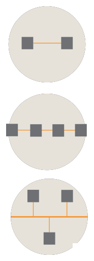
Figure 10.1: Point-to-point (top), line (middle) and bus (bottom).
- Point-to-point: the simplest connection, between two devices. The key disadvantage is that a device that must talk to several others needs a separate connection to each.
- Line: devices connected in series form a line, also called a bus topology. All devices are connected to one transmission medium. Classic fieldbus systems such as PROFIBUS use this topology.
- Bus: all stations share a trunk line with termination points. Information is accessed simultaneously and accepted by the relevant unit. Adopted in IEEE 802.3 (Ethernet) and the IEEE 802.4 Manufacturing Automation Protocol (MAP) standards.
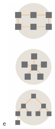
Figure 10.2: Ring (top), star (middle) and tree (bottom).
- Ring: every device can communicate with every other device over two channels (clockwise and counterclockwise). The main advantage is that communication survives if one section of the network is broken.
- Star: a computer or server is the central hub. It is relatively easy to track data flow and prioritise communications, but the whole system goes down if the central computer crashes, so redundancy is usually built in.
- Tree: several distribution components, depending on size; effectively an “expanded” star. The common office Ethernet network using switches as distribution points is an example.
10.2 Transmission media
| Twisted pair | Coaxial | Fibre optic |
|---|---|---|
 |
 |
 |
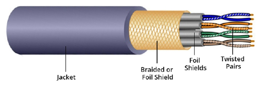
- Twisted pair: two or more insulated wires intertwined and run in parallel. In each pair one line is ground and the other is data. The twisting cancels interference, so it suits short-distance transmission by reducing electromagnetic interference. It is more pliable and easier to install than coaxial cable.
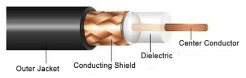
- Coaxial: an inner conductor surrounded by an insulating layer with conductive shielding around it (sometimes with an insulated outer jacket too). The centre conductor carries the signal; the shielding allows fast transmission through the copper core without interference from the environment.
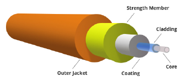
- Fibre optic: the core is optical fibre rather than copper, so data is carried by light rather than an electrical signal. Transmissions travel further, with pulses about 26,000 times faster than twisted pair.
| Characteristic | Twisted pair | Coaxial | Fibre |
|---|---|---|---|
| Data rate | Low | Moderately high | Very high |
| Noise immunity | Low | Higher | Highest |
| Installation | Easy | Fairly easy | Difficult |
| Cost | Cheap | Relatively cheap | Relatively expensive |
| Attenuation | High | Low | Very low |
The main distinguishing feature is data rate. The slides quote twisted pair at a maximum of 10 Mbps, with coaxial up to 80 times faster; optical fibre is used for high-speed transfer, with signals travelling at about 69% of the speed of light.
Modern shielded twisted-pair Ethernet cabling (Cat 6/6A and above) supports 1–10 Gbps over short runs; the 10 Mbps figure applies to older cabling.
10.3 Network components
The fundamental purpose of a network is to send data between two devices (hosts).
| Component | What it does | Picture |
|---|---|---|
| Repeater | Over long distances there are losses on data lines; a repeater amplifies the attenuated signal. |  |
| Hub | Connects multiple hosts on one network; effectively a multi-port repeater. It sends every signal to every host, causing high bandwidth use and poor security. | 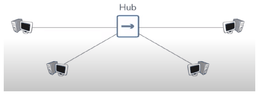 |
| Bridge | Connects two hub-connected groups, keeping each group’s traffic within its own hub network. | 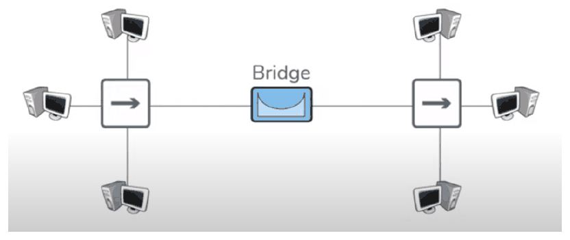 |
| Switch | A combination of hub and bridge: multiple ports like a hub, and it learns which hosts are on each port like a bridge. Switches handle communication within a network. | 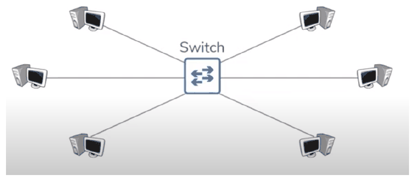 |
| Router | Learns which networks it is attached to and stores the routes in a routing table. Routers handle communication between networks. | 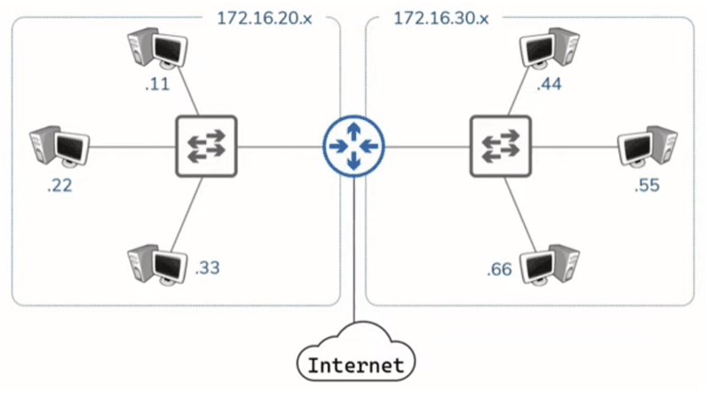 |
| Gateway | A connection point between two different network types, e.g. the link between a facility’s information technology (IT) and operations technology (OT), joining ISA-95 layers 1–3 and 4–5. | 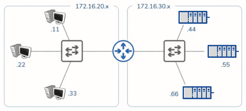 |
Key points
- Line and bus topologies dominate classic fieldbus; rings add tolerance to a single break; stars and trees are typical of office Ethernet.
- Media trade off data rate, noise immunity, cost and ease of installation.
- Hubs repeat to everyone; switches deliver within a network; routers deliver between networks; gateways translate between network types (IT and OT).
Interactive applets
Each applet runs in the page; use Open full screen for more room, or open all of this chapter’s applets together.
Applet 10.1 · Topology builder and failure tester
Place nodes and draw links to build bus, ring, star or tree networks, then click to break a cable or kill a node; reachable nodes stay green and isolated ones turn red.
Teaches: Fault tolerance of each topology (ring survives one break; star dies with its hub). · Open full screen ↗
Applet 10.2 · Cable comparison slider
Choose twisted pair, coax or fibre, set a run length and an electrical-noise level, and watch signal attenuation and bit errors on an animated waveform or eye diagram.
Teaches: Attenuation and noise immunity. · Open full screen ↗
Applet 10.3 · Hub vs switch traffic animation
Send packets between hosts: a hub floods every port, while a switch learns MAC addresses and forwards only to the destination port (its MAC table fills as it learns).
Teaches: Why switches replaced hubs (bandwidth, security). · Open full screen ↗
Applet 10.4 · Router and gateway sandbox
Two subnets (e.g. 172.16.20.x and 172.16.30.x) joined by a router; the learner fills in the routing table, then adds an OT network behind a gateway.
Teaches: Within-network vs between-network delivery, and the IT/OT boundary. · Open full screen ↗