Lecture 17: Synchronous Motors
The Synchronous Motor
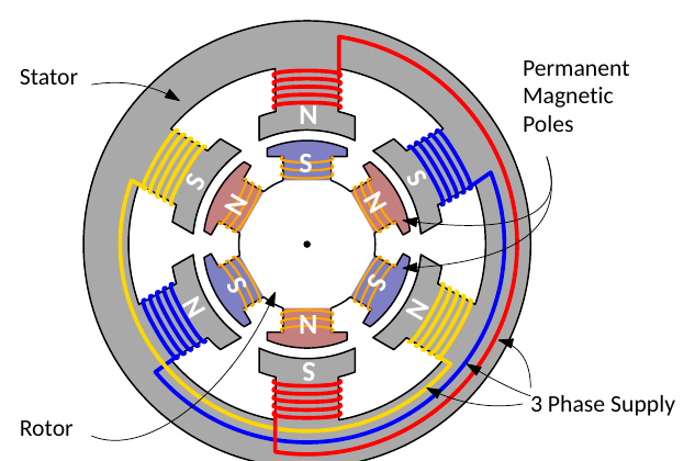
- The synchronous motor runs at a constant speed from no load to full load.
- A rotating magnetic field is produced when three-phase AC is applied to the stator windings, as in the induction motor.
- Unlike the induction motor, the rotor winding is energised with DC (or the rotor uses permanent magnets). It therefore acts like a bar magnet, and rotates at the same speed as the rotating stator field: the synchronous speed.
- The speed of the rotating field depends on the frequency of the three-phase supply, so if the supply frequency is constant the rotor turns at a constant speed:
\[ N_s = \frac{60\,f}{p} \quad \text{rpm} \]
where \(p\) is the number of pole pairs.
How the Rotor Follows the Field
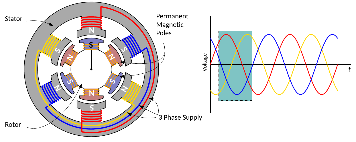
- With the rotor energised from DC, each rotor pole keeps its polarity.
- The highlighted window on the waveforms shows the state of the stator field. Taking a positive half cycle as a north pole and working clockwise from 12 o’clock, the red winding is north, the blue winding south and the yellow winding north.
- Each rotor pole is magnetically aligned with the opposite stator pole.
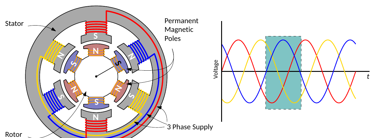
- In the next time window, the red and yellow phases are negative and the blue phase positive: all the stator coils have switched polarity.
- The rotor poles do not change polarity, so the rotor turns to realign itself with the stator poles.
- This repeats every period, so the rotor turns in step with the field.
The highlighted window represents a period of time, not a single instant. In practice the stator poles change polarity gradually and the rotor turns smoothly. This contrasts with the stepper motor (Lecture 5), where coils are rapidly energised and de-energised.
Starting a Synchronous Motor
- Because the rotor turns at the speed of the stator field, its speed stays constant whatever the load: a desirable characteristic for many applications.
- A disadvantage is that a synchronous motor cannot start from standstill simply by applying three-phase AC to the stator. The instant AC is applied, a fast-rotating field sweeps past the rotor poles so quickly that the rotor has no chance to follow: it is pushed first one way and then the other, so a pure synchronous motor has no starting torque.
- A squirrel cage winding is therefore added to the rotor, so that it starts as an induction motor.
- When the rotor is near synchronous speed, the rotor winding is connected to its DC supply and the rotor pulls into step with the rotating field.
- The need for an external DC supply as well as the AC supply makes this type of motor unattractive for many applications.
Load Angle
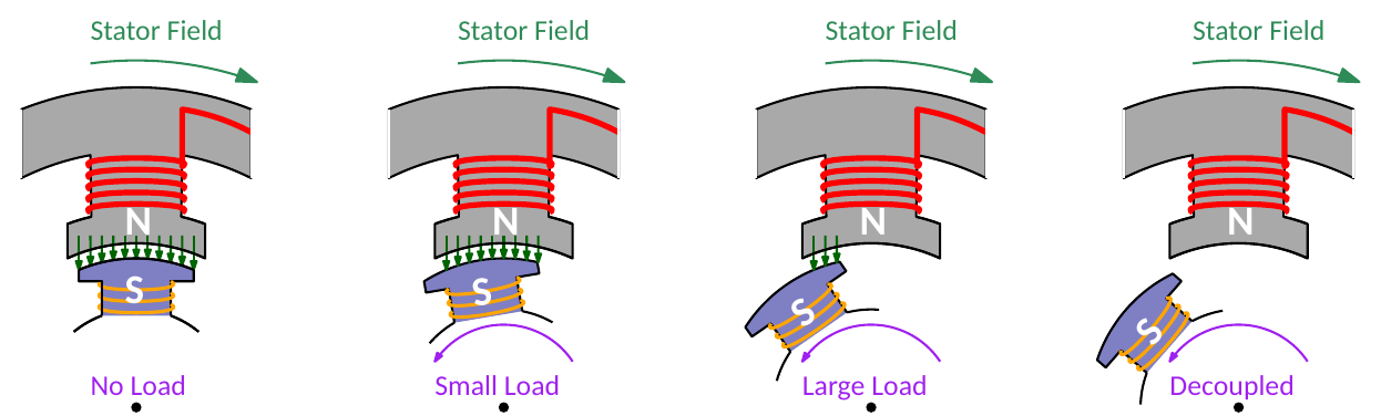
- As the motor is loaded, the rotor lags the stator field by the load angle or coupling angle \(\alpha\). The rotor still turns at synchronous speed; it just runs further behind the field.
- If the load increases too much, \(\alpha\) grows until the flux linkage breaks and the rotor decouples from the field (pulls out of step).
- The rotor speed then falls rapidly, and the motor will either burn out through excessive current or the circuit protection will trip to prevent damage.
Equivalent Circuit and Power
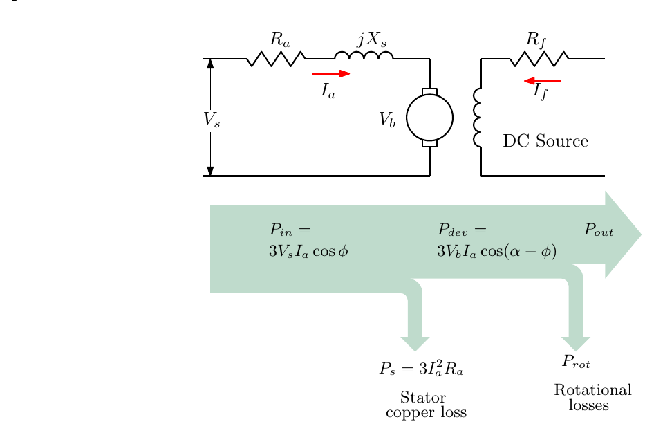
The circuit is similar to that of the DC motor, with the addition of the stator reactance:
\[ V_s = V_b + I_aZ_s, \qquad Z_s = R_a + jX_s \]
where \(V_b\) is the back e.m.f. and \(X_s\) the synchronous reactance. The power flow is
\[ P_{in} = 3V_sI_a\cos\varphi, \qquad P_s = 3I_a^2R_a, \qquad P_{dev} = 3V_bI_a\cos(\alpha - \varphi), \qquad P_{out} = P_{dev} - P_{rot} \]
The input power is as before; note that the load angle \(\alpha\) appears in the developed power.
Simplified equivalent circuit
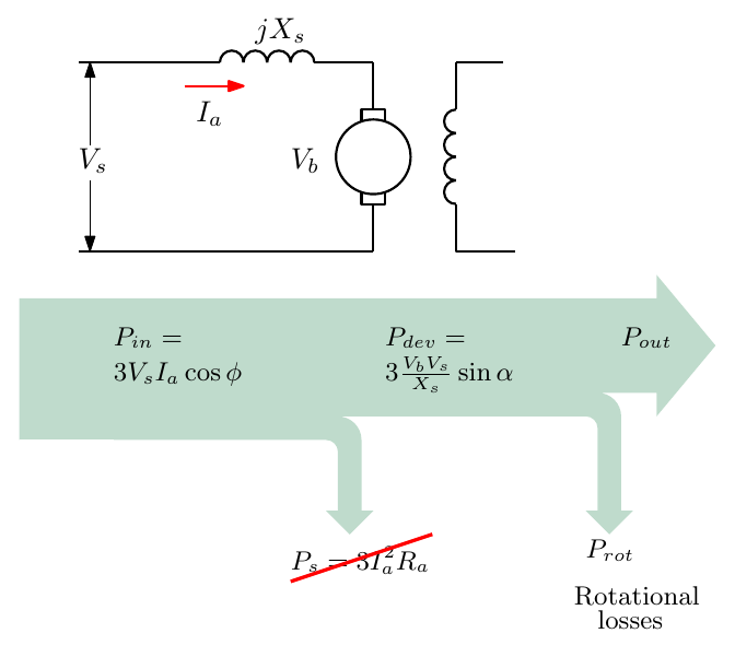
For power calculations on most machines the armature resistance is negligible, so the stator copper loss can be dropped and the developed power becomes
\[ P_{dev} = 3\,\frac{V_bV_s}{X_s}\sin\alpha \]
Torque and the Speed–Torque Curve
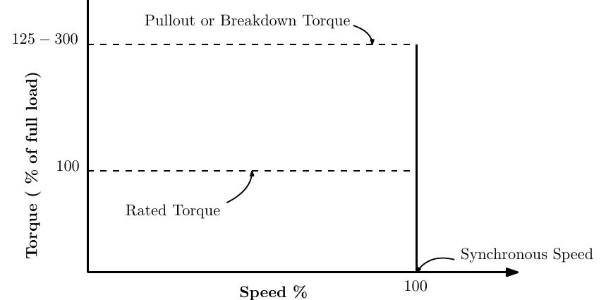
- The rotor turns at the speed of the stator field, so the speed of a synchronous motor is the same at every torque up to its rating: the speed–torque “curve” is a vertical line at synchronous speed.
- Using \(P = T_m\,\omega\) with the developed power above:
\[ T_m = 3\,\frac{V_bV_s}{\omega_s X_s}\sin\alpha \]
- The maximum torque occurs at \(\alpha = 90^\circ\). This is the pull-out (breakdown) torque, typically 125–300% of full-load torque; it is the point just before the rotor magnetically decouples from the stator field.
Worked Example
A three-phase, 6600 V, star-connected synchronous motor delivers 500 kW at full load. Its full-load efficiency is 83%. The armature resistance is 0.3 Ω per phase and the synchronous reactance 3.2 Ω per phase. With a power factor of 0.8 lagging, calculate (a) the back e.m.f. at full load and (b) the load angle.
Phase voltage. Star-connected:
\[ V_{phase} = \frac{V_{line}}{\sqrt{3}} = \frac{6600}{\sqrt{3}} = 3810.5\ \text{V} \]
Input power
\[ \eta = \frac{P_{out}}{P_{in}} \;\Rightarrow\; 0.83 = \frac{500 \times 10^3}{P_{in}} \;\Rightarrow\; P_{in} = 602.4\ \text{kW} \]
Current. \(P_{in} = \sqrt{3}\,V_{line}I_{line}\cos\varphi\):
\[ 602\,400 = \sqrt{3} \times 6600 \times I_{line} \times 0.8 \;\Rightarrow\; I_{line} = 65.87\ \text{A} \]
In star, \(I_{phase} = I_{line}\), and with a power factor of 0.8 lagging (\(\cos^{-1}0.8 = 36.87^\circ\)):
\[ I_a = 65.87\angle -36.87^\circ\ \text{A} \]
Back e.m.f.
\[ Z_s = R_a + jX_s = 0.3 + j3.2\ \Omega = 3.214\angle 84.64^\circ\ \Omega \]
\[ V_b = V_s - I_aZ_s = 3810.5\angle 0^\circ - (65.87\angle -36.87^\circ)(3.214\angle 84.64^\circ) \]
\[ V_b = 3810.5 - 211.7\angle 47.77^\circ = 3810.5 - (142.3 + j156.8) = 3668.2 - j156.8\ \text{V} \]
(a) \(V_b = 3671\angle -2.45^\circ\) V per phase (about 6.36 kV line).
(b) The load angle is the angle by which the back e.m.f. lags (or leads) the supply voltage: \(\alpha \approx 2.5^\circ\).
Rotor Pole Types
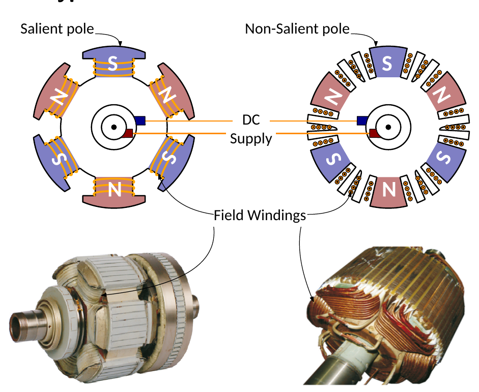
The rotor of a synchronous motor or generator takes one of two main forms.
| Salient pole | Non-salient (cylindrical) pole | |
|---|---|---|
| Shape | Large diameter, short axial length | Smaller diameter, long axial length |
| Speed | Lower speed machines, about 100–1500 rpm | High-speed machines, usually 1500–3000 rpm |
| Flux and e.m.f. waveform | Relatively poor flux distribution, so a less sinusoidal e.m.f. | Sinusoidal flux distribution, giving a better e.m.f. waveform |
| Other | Usually needs extra damper windings to prevent rotor oscillation | Lower windage loss and noise; more robust construction |
| Typical use | Hydro-electric power stations | Nuclear, gas and thermal power stations |
Summary of Motor Types
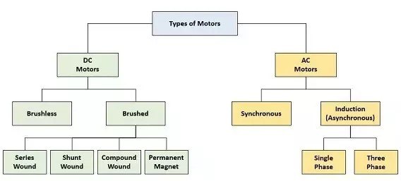
This concludes the motor types covered in this module; the next lecture tidies up speed control and motor starting. These are the most common motor types, but the list is not exhaustive. For example:
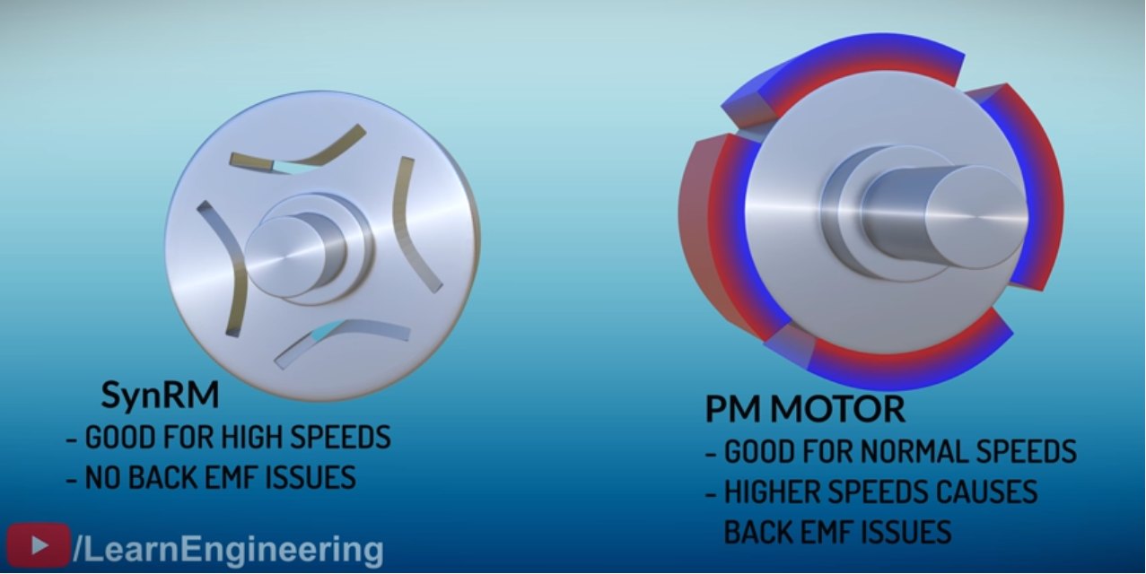
The Tesla Model 3 motor combines ideas from a synchronous reluctance motor (good for high speeds, no back e.m.f. issues) and a permanent magnet motor (good for normal speeds, but higher speeds cause back e.m.f. issues). Image from the Learn Engineering video.
Interactive Elements
Each element below runs in the page; use Open full screen for more room.
Synchronous motor and load angle
A rotating stator field and a DC-excited rotor following it. A load slider increases the load angle \(\alpha\); the torque \(T \propto \sin\alpha\) is plotted with the operating point, and pushing past \(\alpha = 90^\circ\) makes the rotor slip out of step. The speed stays exactly synchronous until then.
Synchronous versus induction motor
The two speed–torque curves side by side under the same load, one holding synchronous speed, the other slowing with slip.
Phasor diagram calculator
Enter \(V_s\), \(I_a\), the power factor, \(R_a\) and \(X_s\) to draw \(V_s\), \(I_aZ_s\) and \(V_b\) as phasors and read off the back e.m.f. and the load angle, with the worked example as a preset.
Starting sequence
Animate start-up: the rotor runs up as an induction motor on its squirrel cage, the DC field is switched on near synchronous speed, and the rotor pulls into step.
Knowledge Check
Q1. How does the rotor of a synchronous motor differ from that of an induction motor?
Answer
It is energised with DC (or uses permanent magnets), so its poles have fixed polarity and it locks onto the rotating stator field. An induction motor’s rotor currents are induced by the stator field.
Q2. A 4-pole synchronous motor runs from a 50 Hz supply. What is its speed at no load and at full load?
Answer
\(N_s = 60 \times 50/2 = 1500\) rpm at both: a synchronous motor runs at synchronous speed at every load up to its pull-out torque.
Q3. Why can a pure synchronous motor not start on its own, and how is the problem solved?
Answer
At switch-on the stator field rotates so fast that the rotor is pulled first one way then the other, giving no net starting torque. A squirrel cage winding is added to the rotor so it starts as an induction motor; near synchronous speed the DC field is switched on and the rotor pulls into step.
Q4. What is the load angle, and what happens if it becomes too large?
Answer
It is the angle by which the rotor lags the stator field, which grows with load. If the load exceeds the pull-out torque (at \(\alpha = 90^\circ\)), the rotor decouples from the field, its speed falls rapidly, and the motor overheats from excessive current unless the protection trips.
Q5. Write the expression for the developed power of a synchronous motor with negligible armature resistance. At what load angle is it greatest?
Answer
\(P_{dev} = 3\dfrac{V_bV_s}{X_s}\sin\alpha\), greatest at \(\alpha = 90^\circ\).
Q6. A synchronous motor has \(V_s = V_b = 400\) V per phase, \(X_s = 10\ \Omega\) and runs at 1500 rpm. What is its pull-out torque?
Answer
\(P_{max} = 3 \times 400 \times 400/10 = 48\) kW and \(\omega_s = 1500 \times \pi/30 = 157.1\) rad/s, so \(T_{max} = 48\,000/157.1 = 306\) N·m.
Q7. In the worked example, the back e.m.f. was 3671 V against a supply of 3810.5 V. Is the back e.m.f. leading or lagging the supply voltage?
Answer
Lagging, by about 2.5° (the load angle), as expected for a motor.
Q8. Compare salient-pole and cylindrical rotors: which would you use for a hydro-electric generator and which for a steam turbine generator, and why?
Answer
Salient pole for hydro: water turbines run slowly (about 100–1500 rpm), and a large-diameter rotor with many poles gives the right frequency at low speed. Cylindrical for steam (thermal, gas, nuclear): the turbines run fast (1500–3000 rpm), and a smaller-diameter, robust cylindrical rotor withstands the high centrifugal forces and gives a sinusoidal e.m.f.
Q9. Why is the need for a DC supply a disadvantage of the wound-field synchronous motor?
Answer
It needs a second, separate DC supply (and usually slip rings and brushes to feed the rotor) as well as the three-phase AC supply, adding cost, complexity and maintenance compared with an induction motor.