PLC Fundamentals and Hardware
Chapter 7 · Part II: Programmable Logic Controllers · Sources: Lectures 6 and 8
7.1 What is a PLC?
PLCs are among the most widely used controllers in automation. The course uses Siemens S7-1200 PLCs.
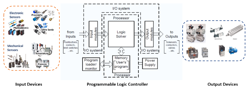
Figure 7.1: A PLC sits between input devices (sensors, switches) and output devices (motors, valves, lamps).
- PLCs are microprocessor-based, and in many respects similar to a PC. The obvious difference is that a PLC has no permanent screen or keyboard; these are connected only while programming.
- A single, relatively small program is stored in memory and executed repeatedly while the PLC is running.
- The PLC scans the inputs from a set of sensors and evaluates their logical relationships to the defined outputs (actuators, relays etc.) according to the program.
- Compared with the response time of the mechanical system, the program runs in milliseconds, so the rungs can be treated as executing simultaneously.
- If inputs change during a scan, this usually isn’t a problem: the next scan follows within a fraction of a second and picks up the new inputs.
The scan cycle
 ┌──────────────┐   ┌───────────────────┐   ┌───────────────┐
 │ Read inputs  │ → │ Execute program   │ → │ Write outputs │ ─┐
 │ (input image)│   │ (rung by rung)    │   │ (output image)│  │
 └──────────────┘   └───────────────────┘   └───────────────┘  │
        ▲                                                       │
        └───────────────────── repeat ──────────────────────────┘
7.2 Advantages of PLCs
- Flexibility. Changing the sequence of events only needs reprogramming, unlike hard-wired relays, which must be rewired. The system can easily be fine-tuned to improve process time and productivity, and modular PLCs can take on more complexity later.
- Set-up. The electrician can wire inputs and outputs before programming, since they can be assigned arbitrarily in the program. Debugging and editing are relatively simple.
- Reliability and maintainability. PLCs use solid-state relays with no moving parts, reducing the chance of failure. This matters because the program runs millions of times over the life of the process. Faults can usually be diagnosed by analysing the power flow and verifying the logic.
- Data collection. PLCs can count operations, quality rejections, machine operating hours etc.
- Input/output options. PLCs are ideal for sending pulsed outputs to drive stepper motors. They can also send data to a screen or printer, though as sophistication grows it becomes hard to tell a PLC from a PC.
- Cost. For complex systems (> 10 relays) a PLC is cheaper than standalone relays, and power consumption and floor space are lower than for hard-wired systems.
7.3 Disadvantages and precautions
- Ease of use can lead to a lack of care and analysis at the design stage, which can cause failures later.
- For safety, always include a master control relay to de-energise all PLC outputs at the push of a button, i.e. a mechanically operated switch, so that any fault in the solid-state electronics can be overridden.
- Allow for sudden loss of power, so that when the outputs de-energise the process is left in a safe state.
7.4 PLC hardware
Input unit
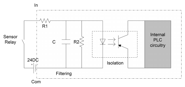
Figure 7.2: Digital input circuit.
- Digital input using a binary signal.
- The sensor relay is usually powered by 24 V DC, though higher-voltage AC is used for very long cable runs.
- The sensor signal is filtered by an RC network (a low-pass filter) to remove transients and noise. This also blocks genuinely high-frequency signals, which need a special input circuit.
- An opto-coupler isolates the internal circuitry, so voltage spikes can’t interfere with or damage it.
- Each input has a status LED. A normally closed input has its LED lit when the input has not been activated.
Output unit
| Type | Switches | Notes |
|---|---|---|
| Relay | AC or DC, up to 2 A | Prone to wear because of moving parts |
| Transistor | DC, up to 1 A | Unidirectional: take care with the polarity of the DC supply |
| Triac | AC, up to 1 A | An RC filter minimises the high-frequency harmonics from switching AC, which would otherwise cause radio-frequency interference and damage the load |
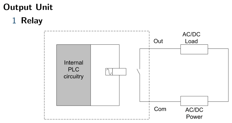
Figure 7.3: Relay output.
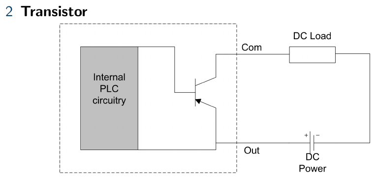
Figure 7.4: Transistor output.
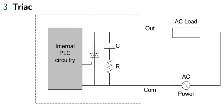
Figure 7.5: Triac output.
For high-power applications, the PLC output must drive a further switching circuit (e.g. a contactor) to control motors, heating elements etc.
Memory allocation
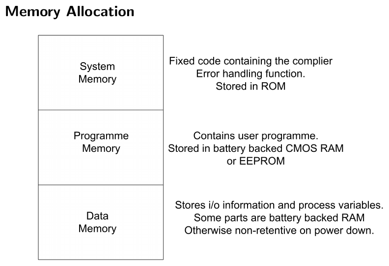
Figure 7.6: PLC memory allocation.
| Area | Contents | Storage |
|---|---|---|
| System memory | Fixed code, including the compiler and error-handling functions | ROM |
| Program memory | The user program | Battery-backed CMOS RAM or EEPROM |
| Data memory | I/O information and process variables | Partly battery-backed RAM; otherwise non-retentive on power-down |
Key points
- A PLC repeatedly reads inputs, executes the program and writes outputs, fast enough to treat the rungs as simultaneous.
- Input circuits filter and isolate; output circuits use relays (AC/DC), transistors (DC) or triacs (AC).
- Always provide a hard-wired master control relay and design for safe power loss.
Interactive applets
Each applet runs in the page; use Open full screen for more room, or open all of this chapter’s applets together.
Applet 7.1 · Scan-cycle visualiser
Watch an animated loop (read inputs → execute → write outputs) with an adjustable scan time; toggle an input mid-scan and see when the change is picked up.
Teaches: Why rungs act “simultaneously”, and the input/output image tables. · Open full screen ↗
Applet 7.2 · Input circuit explorer
Feed a noisy or bouncing switch signal into an RC filter with adjustable R and C; plot raw vs filtered signal and show when the opto-coupler LED turns on.
Teaches: Filtering and isolation; trade-off between noise rejection and response time. · Open full screen ↗
Applet 7.3 · Output module selector
Given a load (AC solenoid 0.5 A, DC motor 3 A, lamp etc.), pick a relay, transistor or triac output; the applet explains why a choice fails (polarity, current, AC/DC).
Teaches: Matching output types to loads. · Open full screen ↗
Applet 7.4 · Relay panel vs PLC cost calculator
Slide the number of relays and see the cost, wiring time and floor space of a relay panel against a PLC.
Teaches: The “> 10 relays” rule of thumb. · Open full screen ↗