Microcontrollers Part 2 — analogWrite, voltage dividers and potentiometers
Learning outcomes
- Understand Pulse Width Modulation (PWM)
- Use the
analogWritefunction to vary voltages - Construct a voltage divider
1. analogWrite
- With
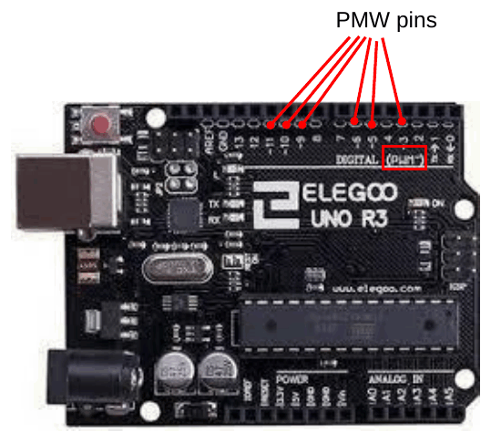
digitalWritewe can only turn a pin on (5 V) or off (0 V). - To get a voltage between 0 and 5 V we use the pins capable of Pulse Width Modulation (PWM) together with
analogWrite(pin, value). - On the Uno the PWM pins are marked with
~: 3, 5, 6, 9, 10, 11.
Voltage resolution
analogWriteuses 8 bits: \(2^8 = 256\) levels, so the value runs from 0 to 255.- 0 → 0 V, 255 → 5 V.
To output a voltage \(V\):
\[\text{value} = \frac{255}{5\ \text{V}} \times V\]
Example: for 1.5 V, \(\frac{255}{5} \times 1.5 = 76.5\) → use 76 or 77 (analogWrite takes whole numbers).
Try it: PWM visualiser — type a voltage and see the analogWrite value, duty cycle, waveform and LED brightness. · Open full screen ↗
2. Exercise 2a — brighten and dim an LED in 1 V steps
Vary the voltage to a red LED in 1 V increments from 1 V up to 5 V and back down again, blinking at each level, and keep repeating.
/*
 * Exercise 2a: Brighten a red LED in 1 V steps from 1 V to 5 V, then dim it
 * back down, and repeat forever.
 * Each level is shown for 0.5 s, then the LED is off for 0.5 s.
 * Hardware: red LED + 220 Ω resistor from D10 (a PWM pin) to GND.
 */

const uint8_t  kRedPin = 10;     // must be a PWM (~) pin for analogWrite
const uint16_t kOnMs   = 500;    // time at each brightness (ms)
const uint16_t kOffMs  = 500;    // LED off between levels (ms)
const float    kVmax   = 5.0;    // pin voltage when the analogWrite value is 255
const int      kPwmMax = 255;    // largest analogWrite value (8 bits)

// Convert a voltage (0 to 5 V) into an analogWrite value (0 to 255).
uint8_t voltsToPwm(float volts) {
  return (uint8_t)(volts / kVmax * kPwmMax + 0.5);   // + 0.5 rounds to the nearest whole number
}

// Show one brightness level, then switch off and report it.
void showLevel(float volts) {
  uint8_t pwm = voltsToPwm(volts);  // e.g. 1 V -> 51
  analogWrite(kRedPin, pwm);        // LED at this brightness
  delay(kOnMs);
  analogWrite(kRedPin, 0);          // LED off
  delay(kOffMs);
  Serial.print(volts);              // prints e.g. "1.00 V -> 51"
  Serial.print(" V -> ");
  Serial.println(pwm);
}

void setup() {
  Serial.begin(9600);               // start the Serial Monitor link
  pinMode(kRedPin, OUTPUT);         // LED pin is an output
}

// loop() repeats forever, so the LED keeps brightening and dimming.
void loop() {
  // Brighten: 1 V up to 5 V
  showLevel(1.0);
  showLevel(2.0);
  showLevel(3.0);
  showLevel(4.0);
  showLevel(5.0);

  // Dim: back down to 2 V. The next pass of loop() starts again at 1 V,
  // so the cycle runs 1-2-3-4-5-4-3-2-1-2-3... without showing 5 V or 1 V twice in a row.
  showLevel(4.0);
  showLevel(3.0);
  showLevel(2.0);
}
Run it: Exercise 2a in the code runner — follow each showLevel() call into voltsToPwm() and watch the LED brighten and dim. · Open full screen ↗
Explainer: what the new pieces do
voltsToPwm(volts)turns the formula above into code: divide by 5 V, multiply by 255. For 1 V: 1 ÷ 5 × 255 = 51.- Decimal points matter.
kVmaxis afloat(5.0), so the division keeps its decimals. If both numbers were whole numbers, as in the slide’s(255/5), C++ does integer division and throws the remainder away:255/5is fine (51), but255/2gives 127, not 127.5. + 0.5then(uint8_t)rounds to the nearest whole number.(uint8_t)keeps only the whole-number part, so adding 0.5 first turns 76.5 into 77 rather than 76.showLevel()holds the five lines that were repeated for every level, so each step is now one line.- Why are the calls in
loop()?setup()runs once, so it only prepares the Serial Monitor and the pin.loop()runs over and over, so putting the calls there makes the LED brighten and dim continually. (The slide usedexit(0)to stop after one run; that isn’t a standard Arduino function and isn’t needed here.) - Why stop the dimming at 2 V? When
loop()finishes it starts again withshowLevel(1.0). Ending the dim at 2 V means 1 V comes next, so each pass ofloop()is one smooth cycle: 1, 2, 3, 4, 5, 4, 3, 2.
3. Exercise 2b — brighten and dim in 0.2 V steps with for loops
0.2 V corresponds to \(\frac{255}{5}\times0.2 \approx 10\) steps of analogWrite value. Use for loops to brighten the LED in these steps, then dim it again, and keep repeating.
/*
 * Exercise 2b: Brighten a red LED from 0 V to about 5 V in steps of about 0.2 V,
 * then dim it back down, using for loops. Repeats forever.
 * Hardware: red LED + 220 Ω resistor from D10 (a PWM pin) to GND.
 */

const uint8_t  kRedPin   = 10;    // PWM (~) pin
const uint16_t kOnMs     = 500;   // time at each brightness (ms)
const uint16_t kOffMs    = 10;    // short gap between levels (ms)
const int      kPwmMax   = 255;   // largest analogWrite value (= 5 V)
const int      kPwmStep  = 10;    // 10 / 255 x 5 V ≈ 0.2 V per step
const int      kTopPwm   = 250;   // highest level: the last step of 10 that fits in 0 to 255

// Show one brightness level, then report it on the Serial Monitor.
void showPwm(int pwm) {
  analogWrite(kRedPin, pwm);           // LED at this brightness
  delay(kOnMs);
  analogWrite(kRedPin, 0);             // brief off
  delay(kOffMs);
  Serial.print(pwm);                   // prints e.g. "50 = 0.98 V"
  Serial.print(" = ");
  Serial.print(pwm * 5.0 / kPwmMax);   // the equivalent voltage
  Serial.println(" V");
}

void setup() {
  Serial.begin(9600);                  // start the Serial Monitor link
  pinMode(kRedPin, OUTPUT);            // LED pin is an output
}

// loop() repeats forever, so the LED keeps brightening and dimming.
void loop() {
  // Brighten: pwm = 0, 10, 20, ... 250
  for (int pwm = 0; pwm <= kTopPwm; pwm += kPwmStep) {
    showPwm(pwm);
  }

  // Dim: pwm = 240, 230, ... 10. The next pass of loop() starts again at 0,
  // so 250 and 0 are never shown twice in a row.
  for (int pwm = kTopPwm - kPwmStep; pwm > 0; pwm -= kPwmStep) {
    showPwm(pwm);
  }
}
Run it: Exercise 2b in the code runner — watch pwm climb in steps of 10, then fall again, and see each loop stop when its test fails (try 4× speed). · Open full screen ↗
Explainer: two for loops, one up and one down
for (int pwm = 0; pwm <= kTopPwm; pwm += kPwmStep)counts up: start at 0; keep going whilepwmis 250 or less; add 10 after each pass.pwm += kPwmStepis shorthand forpwm = pwm + kPwmStep.for (int pwm = kTopPwm - kPwmStep; pwm > 0; pwm -= kPwmStep)counts down: start at 240; keep going whilepwmis more than 0; subtract 10 after each pass. It stops after 10.- Why the dim stops at 10, not 0: when
loop()ends it starts again with the brightening loop at 0. Stopping the dim at 10 means each pass is one smooth cycle (0 → 250 → 10) and neither end is shown twice in a row. One full cycle takes about 25 s. showPwm(pwm)holds the eight lines both loops need, so they are written once.- Why a whole-number counter? The slide counted with a
float. Counting in wholeanalogWritevalues is exact, and the voltage is worked out from it when printing. - Why
intand notuint8_t? Auint8_tcan only hold 0 to 255. If the brightening loop’s test werepwm <= 255, then after 250 the next value, 260, wouldn’t fit and would wrap round to 4. The test would always be true and the loop would never end. Anintholds up to 32 767, so values like this are stored correctly. - Why the top level is 250 (4.9 V): it is the last multiple of 10 that fits in 0–255.
4. Exercise 2c — mimic a voltage drop (fading LEDs)
Mimic a voltage drop over about a minute: dim the red LED; when it gets very low (< 50) dim the green LED, then the blue.
/*
 * Exercise 2c: Mimic a voltage drop. The red LED dims over about 20 s;
 * when its level falls below 50 the green LED takes over, then the blue.
 * The whole sequence lasts about a minute and runs once.
 * Hardware: red, green and blue LEDs, each with a 220 Ω resistor,
 * on PWM pins D10, D9 and D11.
 */

const uint8_t  kRedPin     = 10;    // all three must be PWM (~) pins
const uint8_t  kGreenPin   = 9;
const uint8_t  kBluePin    = 11;
const int      kStartLevel = 255;   // full brightness
const int      kLowLevel   = 50;    // "very low": hand over to the next LED below this
const int      kStepSize   = 5;     // brightness drop per step
const uint16_t kStepMs     = 480;   // time per step: 3 LEDs x 42 steps x 0.48 s ≈ 1 minute

// Dim one LED from full brightness down to kLowLevel, then switch it off.
void fadeDown(uint8_t pin) {
  for (int level = kStartLevel; level >= kLowLevel; level -= kStepSize) {
    analogWrite(pin, level);    // set the brightness
    Serial.println(level);      // show the level on the Serial Monitor
    delay(kStepMs);             // hold it before the next, lower level
  }
  analogWrite(pin, 0);          // fully off before the next LED starts
}

void setup() {
  Serial.begin(9600);
  pinMode(kRedPin, OUTPUT);
  pinMode(kGreenPin, OUTPUT);
  pinMode(kBluePin, OUTPUT);

  fadeDown(kRedPin);            // red first ...
  fadeDown(kGreenPin);          // ... then green ...
  fadeDown(kBluePin);           // ... then blue
}

void loop() {
  // Nothing to repeat.
}
Run it: Exercise 2c in the code runner — watch fadeDown() dim each LED in turn (try 4× speed). · Open full screen ↗
Explainer: counting down with a function
fadeDown(pin)contains the dimming code once. Calling it three times with different pins replaces the slide’s three almost identical loops.level -= kStepSizesubtracts 5 each pass, solevelgoes 255, 250, 245 … 55, 50. Counting down is what makes it look like a falling voltage.level >= kLowLevelstops the fade once the level would drop below 50, the point where the task says the next LED should take over.- Why
intagain? Iflevelwere auint8_tand the test werelevel >= 0, it could never fail: going below 0 wraps round to 255, so the loop would never finish. Anintcan go negative, so tests like this behave as expected. - Timing: 255 → 50 in steps of 5 is 42 steps; 42 × 0.48 s ≈ 20 s per LED, so about a minute for all three. Change
kStepMsto make it faster or slower.
5. Ohm’s law revision
\[V = IR\]
Single resistor: \(V_s = 12\ \text{V}\), \(R = 330\ \Omega\) → \(I = \frac{12}{330} = 36\ \text{mA}\).
Two resistors in series: resistances add, \(R_T = R_1 + R_2\). With \(R_1 = R_2 = 330\ \Omega\): \(R_T = 660\ \Omega\) and \(I = \frac{12}{660} = 18\ \text{mA}\).
The voltage across each resistor: \(V_1 = IR_1 = (18\times10^{-3})(330) = 6\ \text{V}\).
6. The voltage divider
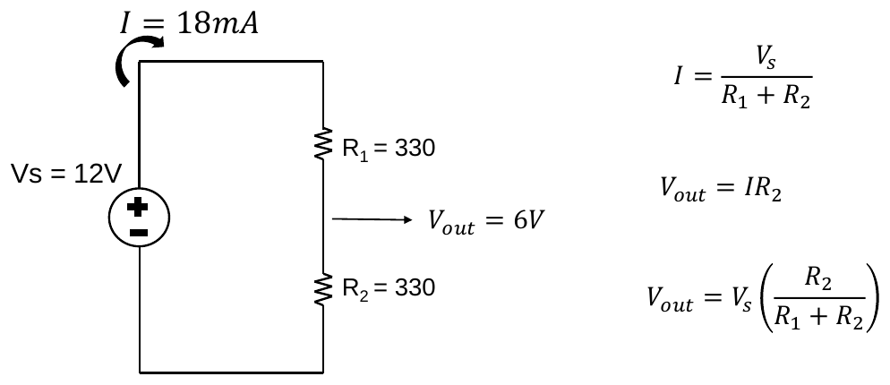
\[I = \frac{V_s}{R_1 + R_2}, \qquad V_{out} = IR_2 \quad\Rightarrow\quad \boxed{V_{out} = V_s\,\frac{R_2}{R_1 + R_2}}\]
Exercise — design a divider
Design, build and test a voltage divider with an output of 6 V and a current of 60 mA from a 12 V battery.
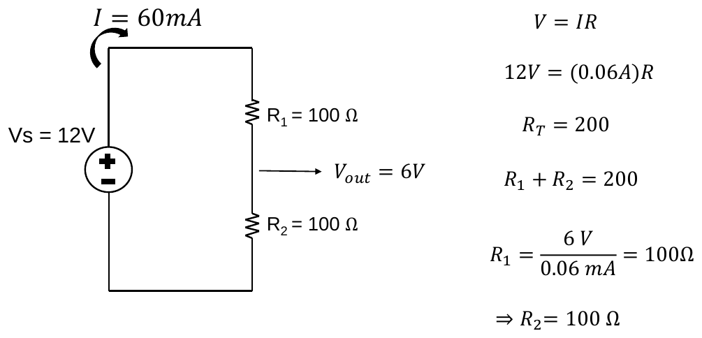
- Total resistance: \(R_T = \frac{V_s}{I} = \frac{12}{0.06} = 200\ \Omega\)
- Voltage across \(R_2\) must be 6 V: \(R_2 = \frac{6\ \text{V}}{0.06\ \text{A}} = 100\ \Omega\)
- \(R_1 = R_T - R_2 = 100\ \Omega\)
⚠️ The slide writes \(0.06\ \text{mA}\) in step 2 — it should be 0.06 A (60 mA).
Each 100 Ω resistor dissipates \(P = I^2R = 0.06^2\times100 = 0.36\ \text{W}\) — more than a standard ¼ W resistor can handle. Use ½ W resistors (or larger values / lower current).
Try it: Voltage divider lab — “Design” tab reproduces this calculation for any \(V_s\), \(V_{out}\) and \(I\). · Open full screen ↗
7. Potentiometers
A potentiometer (“pot”) can be thought of as a variable resistor — or, more usefully, as a voltage divider whose split you can adjust by turning a knob.
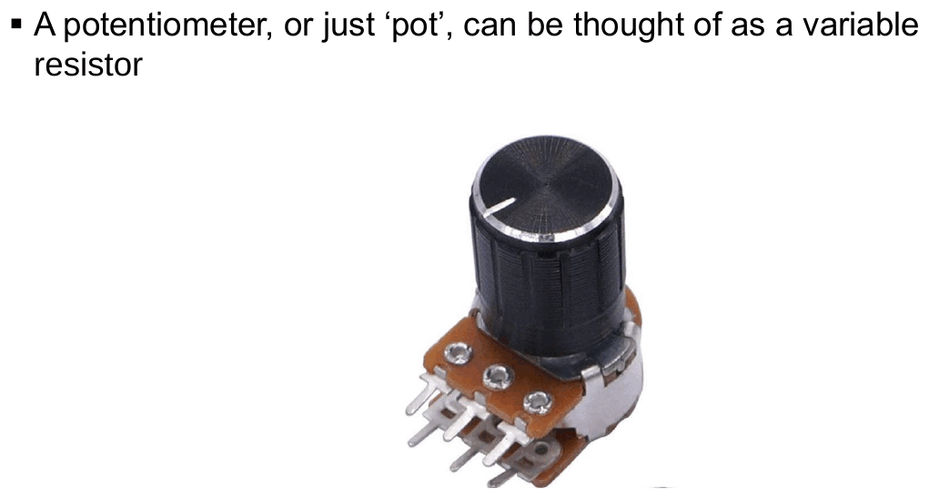
It has three pins: the two outer pins are the ends of a fixed resistance track (\(R_{tot}\), here 5 kΩ) and the middle pin is the wiper, which divides the track into \(R_1\) and \(R_2\):
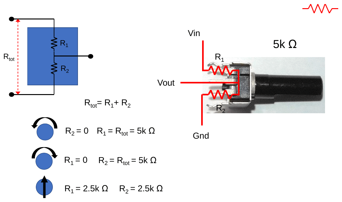
| Knob position | \(R_1\) | \(R_2\) |
|---|---|---|
| Fully one way | \(R_{tot} = 5\ \text{k}\Omega\) | 0 |
| Fully the other way | 0 | \(R_{tot} = 5\ \text{k}\Omega\) |
| Middle | 2.5 kΩ | 2.5 kΩ |
With 5 V across a 5 kΩ pot:
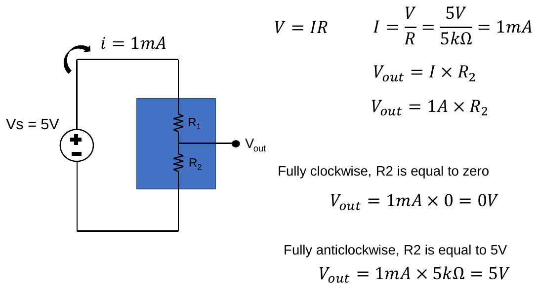
\[I = \frac{5\ \text{V}}{5\ \text{k}\Omega} = 1\ \text{mA}, \qquad V_{out} = I \times R_2\]
- Fully clockwise, \(R_2 = 0\): \(V_{out} = 1\ \text{mA}\times0 = 0\ \text{V}\)
- Fully anticlockwise, \(R_2 = 5\ \text{k}\Omega\): \(V_{out} = 1\ \text{mA}\times5\ \text{k}\Omega = 5\ \text{V}\)
⚠️ Slide typos: “\(V_{out} = 1\ \text{A}\times R_2\)” should be 1 mA, and “R2 is equal to 5 V” should be 5 kΩ. The “Ohm’s law revision” slide for the 5 V pot circuit also repeats the 12 V / 330 Ω calculation from earlier — ignore it.
8. Potentiometer exercises
| Exercise | Task |
|---|---|
| 2d | Build a circuit and write a programme that reads in voltage values that vary when using a potentiometer. |
| 2d1 | Increase and decrease the brightness of a red LED using the pot. |
| 2d2 | Turn on a blue LED above 2.5 V and off below 2.5 V. |
| 2e | Red LED on for 0–2 V, green for > 2–3.5 V, blue for > 3.5–5 V. |
Full worked solutions and circuit photos are in Part 6 — Potentiometers. The key new function is:
const uint8_t kPotPin = A1;                  // pot wiper connected to analogue pin A1

int   reading = analogRead(kPotPin);         // 10-bit result: 0 to 1023
float volts   = reading * (5.0 / 1023.0);    // convert the reading to volts
analogRead returns a whole number from 0 (0 V) to 1023 (5 V). Multiplying by 5.0 / 1023.0 converts it back to volts; the decimal points make sure the division keeps its fractional part.
Try it: Potentiometer applet — turn the knob and switch between exercises 2d, 2d1, 2d2 and 2e. · Open full screen ↗
Key points
analogWrite(pin, 0–255)on a~pin gives an average voltage of \(5 \times \text{value}/255\).- Series resistors add; current is the same through each; voltages divide in proportion to resistance.
- \(V_{out} = V_s R_2/(R_1+R_2)\) — the basis of every sensor/voltage-monitoring circuit in the project.
- A pot is an adjustable voltage divider; read it with
analogRead(0–1023).