Lecture 10: Transformers
The Ideal Transformer
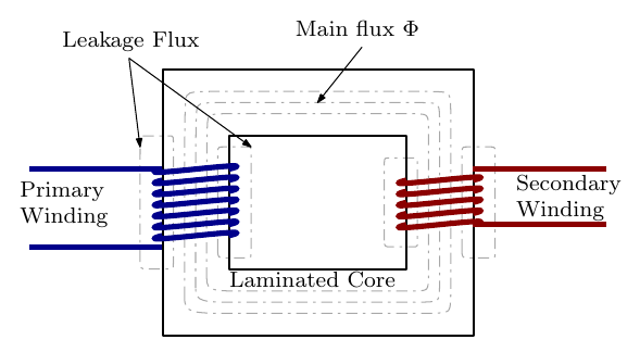
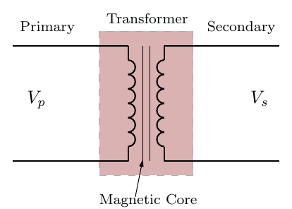
The fundamental operation of a transformer:
- An AC voltage is applied to the primary winding.
- This induces a flux \(\Phi\) in the steel core.
- This flux induces an e.m.f. in the secondary winding.
- The e.m.f. induced in each winding is proportional to its number of turns, so
\[ \frac{V_p}{V_s} = \frac{N_p}{N_s} = \frac{I_s}{I_p} \]
where \(N_p\) and \(N_s\) are the numbers of turns on the primary and secondary sides.
Step-down and step-up transformers
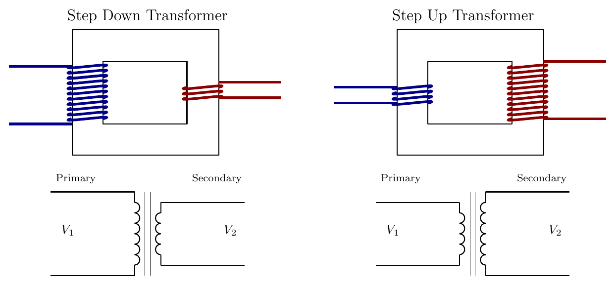
\[ \frac{V_1}{V_2} = \frac{N_1}{N_2} \quad \Rightarrow \quad V_2 = V_1\,\frac{N_2}{N_1} \]
The turns ratio dictates the output voltage. In the ideal case the power is the same on the primary and secondary sides, so if the voltage on one side rises relative to the other, the current falls by the same ratio, since \(S = IV\).
Example
A single-phase transformer has a primary to secondary turns ratio of 5 : 1 and is supplied at 1 kV. A resistive load of 5 Ω is connected across the secondary winding. Find the primary current and the active power supplied by the transformer.
\[ V_2 = V_1\,\frac{N_2}{N_1} = \frac{1000 \times 1}{5} = 200\ \text{V}, \qquad I_2 = \frac{V_2}{R} = \frac{200}{5} = 40\ \text{A} \]
\[ I_1 = I_2\,\frac{N_2}{N_1} = \frac{40 \times 1}{5} = 8\ \text{A}, \qquad P_1 = I_1 V_1 = 8 \times 1000 = 8\ \text{kW} \]
Here \(P_1 = P_2\) because there are no losses and the load is purely resistive. This is typically not the case in practice.
The Non-ideal Transformer
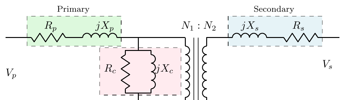
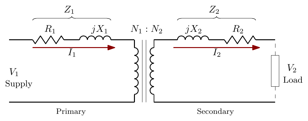
The losses in a real transformer are modelled by:
- Primary winding losses \((R_p + jX_p)\): resistive and inductive (leakage) losses in the primary winding.
- Secondary winding losses \((R_s + jX_s)\): resistive and inductive losses in the secondary winding.
- Additional losses \(R_c\,//\,jX_c\), made up of:
- core flux losses,
- hysteresis losses,
- eddy current losses.
The no-load current of a transformer is only about 3–5% of the full-load primary current, so leaving out \(R_c\) in parallel with \(X_c\) simplifies the model without appreciable error when studying the transformer on full load:
Referring the Secondary to the Primary
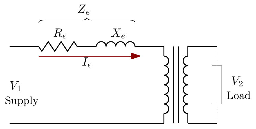
To simplify the circuit further, all the secondary components are referred (reflected) to the primary side, so that the power absorbed when carrying the primary current is the same as when carrying the secondary current.
Replace \(R_2\) by a resistor \(R_2'\) on the primary side such that both dissipate the same power (the load “sees” no difference):
\[ I_1^2 R_2' = I_2^2 R_2 \quad \Rightarrow \quad R_2' = R_2\left(\frac{I_2}{I_1}\right)^2 \simeq R_2\left(\frac{V_1}{V_2}\right)^2 \]
The resistances are then in series, so the equivalent resistance referred to the primary is
\[ R_e = R_1 + R_2' = R_1 + R_2\left(\frac{V_1}{V_2}\right)^2 \]
and similarly the equivalent reactance is
\[ X_e = X_1 + X_2' = X_1 + X_2\left(\frac{V_1}{V_2}\right)^2 \]
The equivalent impedance of the primary and secondary windings referred to the primary circuit is
\[ Z_e = \sqrt{R_e^2 + X_e^2} \]
If \(\varphi_e\) is the phase difference between \(I_1\) and \(I_1Z_e\), then
\[ R_e = Z_e\cos\varphi_e, \qquad X_e = Z_e\sin\varphi_e \]
Transformer Efficiency
The losses in a transformer on load fall into two groups:
- \(I^2R\) (copper) losses in the primary and secondary windings, \(I_1^2R_1 + I_2^2R_2\). These vary with the load.
- Core losses due to hysteresis and eddy currents. These can be assumed constant and are denoted \(P_c\).
\[ \text{Total losses} = P_c + I_1^2R_1 + I_2^2R_2 \]
\[ \eta = \frac{\text{output power}}{\text{input power}} = \frac{\text{input power} - \text{losses}}{\text{input power}} = 1 - \frac{\text{losses}}{\text{input power}} \]
\[ \eta = \frac{(I_2V_2 \times \text{pf}) - (P_c + I_1^2R_1 + I_2^2R_2)}{I_2V_2 \times \text{pf}} \]
Example
The primary and secondary windings of a 500 kVA transformer have resistances of 0.42 Ω and 0.0019 Ω respectively. The primary and secondary voltages are 11 000 V and 400 V, and the core loss is 2.9 kW. Assuming the power factor of the load to be 0.8, calculate the efficiency on (a) full load and (b) half load.
(a) Full load
\[ I_2 = \frac{500 \times 1000}{400} = 1250\ \text{A}, \qquad I_1 = \frac{500 \times 1000}{11\,000} = 45.5\ \text{A} \]
\[ \text{Secondary } I^2R \text{ loss} = 1250^2 \times 0.0019 = 2969\ \text{W}, \qquad \text{Primary } I^2R \text{ loss} = 45.5^2 \times 0.42 = 870\ \text{W} \]
\[ \text{Total } I^2R \text{ loss} = 3839\ \text{W} = 3.84\ \text{kW}, \qquad \text{Total loss} = 3.84 + 2.9 = 6.74\ \text{kW} \]
\[ \text{Output power} = 500 \times 0.8 = 400\ \text{kW}, \qquad \text{Input power} = 400 + 6.74 = 406.74\ \text{kW} \]
\[ \eta_{full} = 1 - \frac{6.74}{406.74} = 98.3\% \]
(b) Half load. The \(I^2R\) loss varies as the square of the current:
\[ I^2R \text{ loss} = 3.84 \times 0.5^2 = 0.96\ \text{kW}, \qquad \text{Total loss} = 0.96 + 2.9 = 3.86\ \text{kW} \]
\[ \eta_{half} = 1 - \frac{3.86}{200 + 3.86} = 1 - \frac{3.86}{203.86} = 98.1\% \]
The core loss is the same at every load, so at light loads it makes up a larger share of the input and the efficiency falls slightly.
Interactive Elements
Each element below runs in the page; use Open full screen for more room.
Turns ratio explorer
Adjust \(N_1\) and \(N_2\) (step up or step down), the supply voltage and a load resistance; the primary and secondary voltages and currents update, the flux is animated in the core, and the power is shown to be equal on both sides for the ideal transformer.
Referring impedances
Enter \(R_1, X_1, R_2, X_2\) and the voltage ratio; the secondary components slide across to the primary side scaled by \((V_1/V_2)^2\), and \(R_e\), \(X_e\), \(Z_e\) and \(\varphi_e\) are worked out.
Efficiency against load
For the 500 kVA example, plot copper loss (rising with the square of load), core loss (constant) and efficiency from no load to 125% load, with a power factor slider. Students find that the efficiency peaks where copper loss equals core loss: here at about \(\sqrt{2.9/3.84} \approx 87\%\) of full load.
Knowledge Check
Q1. A transformer has 400 primary turns and 100 secondary turns and is supplied at 240 V. What is the secondary voltage? Is it a step-up or step-down transformer?
Answer
\(V_2 = V_1 N_2/N_1 = 240 \times 100/400 = 60\) V: a step-down transformer.
Q2. In an ideal transformer, if the secondary voltage is ten times the primary voltage, how does the secondary current compare with the primary current? Why?
Answer
It is one tenth of the primary current. An ideal transformer has no losses, so the power (or apparent power, \(S = IV\)) is the same on both sides; if \(V\) rises ten-fold, \(I\) must fall ten-fold.
Q3. Why does a transformer only work with AC, not with a steady DC supply?
Answer
The secondary e.m.f. is induced by a changing flux (Faraday’s law). A steady DC current produces a constant flux, so no e.m.f. is induced in the secondary (apart from at switch-on).
Q4. Name the losses represented by each part of the non-ideal transformer equivalent circuit.
Answer
\(R_p + jX_p\): primary winding resistance and leakage reactance. \(R_s + jX_s\): secondary winding resistance and leakage reactance. \(R_c\,//\,jX_c\): core losses (core flux, hysteresis and eddy currents).
Q5. Why can the parallel core branch \(R_c\,//\,jX_c\) usually be left out when analysing a transformer on full load?
Answer
The no-load (magnetising and core loss) current is only about 3–5% of the full-load primary current, so neglecting it introduces little error.
Q6. A secondary winding resistance of 0.01 Ω is referred to the primary of a 2000 V / 200 V transformer. What is its referred value?
Answer
\(R_2' = R_2(V_1/V_2)^2 = 0.01 \times (2000/200)^2 = 0.01 \times 100 = 1\ \Omega\).
Q7. Which transformer losses depend on the load, and which do not?
Answer
The copper (\(I^2R\)) losses depend on the load, varying with the square of the current. The core losses (hysteresis and eddy currents) are approximately constant at any load.
Q8. In the 500 kVA example, what would the efficiency be on full load at unity power factor?
Answer
The losses are unchanged (6.74 kW), but the output is now 500 kW, so \(\eta = 1 - \dfrac{6.74}{506.74} = 98.7\%\).
Q9. In the 5 : 1 transformer example, the load resistor is changed to 10 Ω. Find the new primary current and power.
Answer
\(V_2\) is still 200 V, so \(I_2 = 200/10 = 20\) A, \(I_1 = 20/5 = 4\) A and \(P_1 = 4 \times 1000 = 4\) kW.
Q10. Why are transformer cores laminated?
Answer
To reduce eddy current losses. The thin, insulated laminations break up the circulating current paths induced in the core by the changing flux.