Microcontrollers Part 3 — Loops, alarms and Pulse Width Modulation
Learning outcomes
- Apply
forloops andifstatements in Arduino code - Understand Pulse Width Modulation
- Use the
analogWritefunction to vary voltages
Part 3 consolidates Parts 1 and 2. The LED exercises (1c, 1d, 1f) and the analogWrite exercises (2a, 2b, 2c) are repeated. Their solutions are in Part 1 and Part 2. The new material is the alarm and a fuller explanation of PWM.
1. Recap — LED exercises
- 1c Blink red ×2, green ×3, blue ×4 (0.5 s). See Part 1, Exercise 1c (written out with
digitalWriteanddelay). - 1d Change the delay to 1 s and move red from pin 13 to pin 10. With named constants this is a two-line change:
kHalfPeriodMs = 1000andkRedPin = 10. - 1f Use a
forloop to do the same. See Part 1, Exercise 1c(2).
2. Add an alarm to the system
Programme the buzzer to sound while the red LED is flashing.
- The buzzer operates between 3.3 and 5 V — a digital pin’s 5 V HIGH is fine.
- Do not put the buzzer on the same circuit as the LED; give it its own output pin. (Sharing a pin puts the buzzer and LED in series or parallel, so neither gets the right voltage/current, and you can’t control them independently.)
/*
 * Part 3 alarm: the red LED flashes 2 times with the buzzer sounding,
 * then green flashes 3 times and blue 4 times without the buzzer. Repeats.
 * Hardware: LEDs + 220 Ω resistors on D10 (red), D12 (green), D11 (blue);
 * active buzzer from D8 to GND.
 */

const uint8_t  kRedPin       = 10;    // red LED
const uint8_t  kGreenPin     = 12;    // green LED
const uint8_t  kBluePin      = 11;    // blue LED
const uint8_t  kBuzzerPin    = 8;     // the buzzer has its own output pin
const uint16_t kHalfPeriodMs = 500;   // on time = off time (ms)

// Flash one LED 'count' times. If withAlarm is true, the buzzer sounds too.
void blink(uint8_t pin, uint8_t count, bool withAlarm) {
  for (uint8_t i = 1; i <= count; ++i) {
    digitalWrite(pin, HIGH);                 // LED on
    if (withAlarm) {
      digitalWrite(kBuzzerPin, HIGH);        // buzzer on, only for the alarm
    }
    delay(kHalfPeriodMs);

    digitalWrite(pin, LOW);                  // LED off
    digitalWrite(kBuzzerPin, LOW);           // buzzer off (harmless if already off)
    delay(kHalfPeriodMs);
  }
}

void setup() {
  pinMode(kRedPin, OUTPUT);                  // all four pins are outputs
  pinMode(kGreenPin, OUTPUT);
  pinMode(kBluePin, OUTPUT);
  pinMode(kBuzzerPin, OUTPUT);
}

void loop() {
  blink(kRedPin,   2, true);     // red with the alarm
  blink(kGreenPin, 3, false);    // green, silent
  blink(kBluePin,  4, false);    // blue, silent
}
Run it: the alarm in the code runner — see the if (withAlarm) line switch the buzzer on only for red (turn your sound on). · Open full screen ↗
Explainer: switching the buzzer on only when needed
bool withAlarmis a yes/no parameter. Aboolholds justtrueorfalse.if (withAlarm) { ... }runs the lines inside the braces only whenwithAlarmistrue. For the red LED we passtrue, so the buzzer sounds; for green and blue we passfalse, so that line is skipped.- Switching the buzzer off every time is simpler than adding a second
if: writingLOWto a pin that is alreadyLOWchanges nothing. - One function, three calls. Each line in
loop()reads like the task itself: which LED, how many times, alarm or not.
💡 An active buzzer beeps when given a steady HIGH. A passive buzzer needs a changing signal — use
tone(kBuzzerPin, 2000);andnoTone(kBuzzerPin);instead ofdigitalWrite.
Try it: Blink sequencer — tick “Sound buzzer” to add the alarm to the generated code (and optionally hear it). · Open full screen ↗
3. Pulse Width Modulation (PWM)
digitalWritecan only give 5 V (on) or 0 V (off).- To get an in-between voltage, the PWM pins switch on and off very quickly (≈ 490 Hz on most Uno pins, 980 Hz on pins 5 and 6).
- PWM controls the power delivered to a device by varying the width of the digital pulses.
- It is used for motor speed control, LED dimming and audio signal generation.
Duty cycle
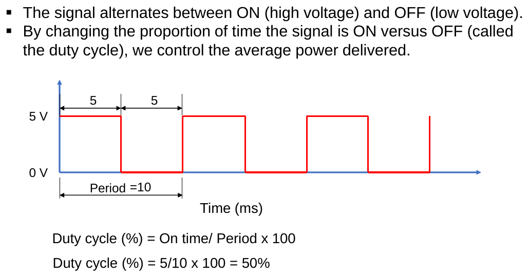
The signal alternates between ON (high voltage) and OFF (low voltage). The proportion of each period that the signal is ON is the duty cycle:
\[\text{Duty cycle (\%)} = \frac{\text{on time}}{\text{period}} \times 100\]
50 % duty cycle — on 5 ms, off 5 ms, period 10 ms: \(\frac{5}{10}\times100 = 50\%\)
75 % duty cycle — on 7.5 ms, off 2.5 ms: \(\frac{7.5}{10}\times100 = 75\%\)
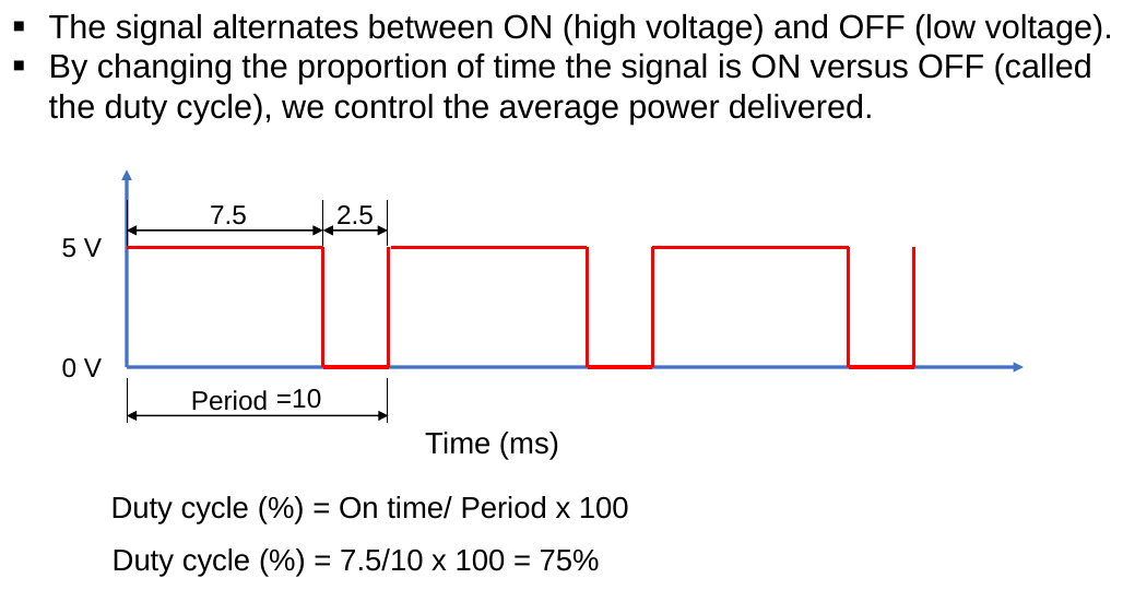
The average voltage is \(V_{avg} = \text{duty} \times 5\ \text{V}\): 2.5 V at 50 %, 3.75 V at 75 %. An LED switching this fast looks steadily dimmer to our eyes; a motor’s inertia smooths the pulses into a lower speed.
Relating duty cycle to analogWrite
\[\text{duty} = \frac{\text{value}}{255}, \qquad V_{avg} = 5\ \text{V}\times\frac{\text{value}}{255}\]
analogWrite value |
Duty cycle | Average voltage |
|---|---|---|
| 0 | 0 % | 0 V |
| 64 | 25 % | 1.25 V |
| 128 | 50 % | 2.5 V |
| 191 | 75 % | 3.75 V |
| 255 | 100 % | 5 V |
PWM pins on the Uno: ~3, ~5, ~6, ~9, ~10, ~11 (8-bit, 0–255).
Try it: PWM visualiser — drag the slider to see the waveform, duty cycle and average voltage; click pins to check which support PWM. · Open full screen ↗
4. Recap — analogWrite exercises
| Exercise | Task | Solution |
|---|---|---|
| 2a | Increase red LED voltage 1 V → 5 V in 1 V steps | Part 2 §2 |
| 2b | Same with a for loop in 0.2 V steps |
Part 2 §3 |
| 2c | Mimic a voltage drop over ~1 minute across red → green → blue | Part 2 §4 |
Key points
- Give each output device (LED, buzzer) its own pin.
- PWM = fast on/off switching; duty cycle sets the average voltage.
analogWrite(pin, value): value 0–255 ↔︎ 0–100 % duty ↔︎ 0–5 V average.