Pump drive type
Chapter 5 · Introduction to microcontrollers
The last block in the project overview is the pump drive type: how the selected supply is applied to the pump. The RenewableSwitchOver board offers two ways, chosen with jumpers:
- Direct drive: the pump is connected straight to the switched supply, at full voltage, the moment the supply is switched in.
- Slow start: the pump is driven through an L298N H-bridge, and the Arduino ramps its voltage up with PWM over a second or two.
The difference that matters most is the inrush current: the surge a motor draws when it starts, or when its supply suddenly jumps. This chapter explains where that surge comes from, then compares the two drive types.
Learning outcomes
By the end of this chapter you should be able to:
- Explain why a DC motor draws a large inrush current at start-up and when its supply voltage steps up
- Describe the advantages and disadvantages of direct drive
- Use PWM and
analogWriteto vary the average voltage applied to a load - Explain how the L298N drives the pump on the project board
- Write a non-blocking slow-start ramp, and compare it with direct drive
1. Inrush current
A small DC pump is a permanent-magnet DC motor. While it turns, it acts as a generator as well as a motor: it produces a back-EMF, \(E\), that opposes the supply and rises with speed. The current is set by the difference between the supply and the back-EMF, across the winding resistance \(R\):
\[I = \frac{V - E}{R}\]
- Running at speed, \(E\) is close to \(V\), so only a small current flows: just enough to overcome friction and the load of the water.
- At standstill, \(E = 0\), so the current is limited only by the winding resistance (and the wiring): \[I_{start} = \frac{V}{R}\]
Example: a 12 V pump with a winding resistance of 2 Ω that runs at 0.8 A. At switch-on it draws \(12 / 2 = 6\) A: more than seven times its running current, until it speeds up and the back-EMF builds. Measure your own pump’s winding resistance with a multimeter (with the pump unpowered) to estimate its start-up current.
A supply step causes a surge too
The same thing happens when the pump is already running and its supply jumps. Running from the RES at 8 V, the pump’s back-EMF settles a little below 8 V. Switch to the 12 V battery and the extra 4 V appears straight across the winding resistance:
\[\Delta I \approx \frac{V_{new} - V_{old}}{R} = \frac{12 - 8}{2} = 2\ \text{A}\]
on top of the running current, until the pump speeds up to match. Switching to a lower voltage does the opposite: the current briefly falls (it can even reverse for a moment) while the pump slows down. Only a step up causes a surge.
Why the surge matters in this project
- The RES voltage sags. A solar panel or small turbine can’t deliver amps without its voltage dropping. A start-up surge can pull the RES below the switch-over threshold, so the Arduino switches to the battery, the RES recovers, it switches back, and the pump is hit again: an oscillation that hysteresis alone may not stop.
- Stress on the parts. Diodes D1/D2 (1N5400: 3 A continuous), the MOSFETs, the battery, connectors and wiring all carry the peak. The L298N is rated at 2 A continuous per channel, with a short non-repetitive peak of 3 A: a 6 A start is well beyond it.
- Mechanical shock. A pump that jumps to full speed jolts its mounting and can cause water hammer in the pipework.
2. Direct drive
In direct drive the jumpers connect the pump straight to the supply: M1 to VPump and M2 to ground. The L298N is bypassed, and the pump runs whenever a supply is switched in. The switching code in Switching circuitry is all it needs.
| Advantages | Disadvantages |
|---|---|
| Simple: no driver, no PWM, no extra code | Full inrush current at every start: several times the running current |
| No extra voltage loss: the pump gets VPump (only the diode drop is lost) | A surge at every switch-over to a higher supply |
| Full torque immediately, useful for a pump that needs a kick to start | Surges can sag the RES below the threshold and cause repeated switching |
| Silent: no PWM whine | Stresses the diodes, MOSFETs, battery and wiring; mechanical shock and water hammer |
| Fails safe: no code is needed to keep the pump running | No speed control: the pump runs at whatever the supply voltage gives |
3. PWM: an average voltage from a digital pin
A slow start needs a voltage that rises gradually. An Arduino pin can only be on (5 V) or off (0 V), but it can switch between them very quickly. That is Pulse Width Modulation (PWM).
Duty cycle
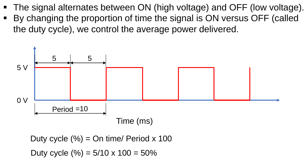
The signal alternates between ON and OFF. The proportion of each period that the signal is ON is the duty cycle:
\[\text{Duty cycle (\%)} = \frac{\text{on time}}{\text{period}} \times 100\]
50 % duty cycle — on 5 ms, off 5 ms, period 10 ms: \(\frac{5}{10}\times100 = 50\%\)
75 % duty cycle — on 7.5 ms, off 2.5 ms: \(\frac{7.5}{10}\times100 = 75\%\)
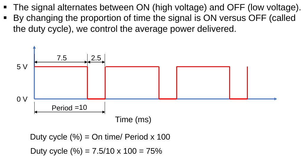
The average voltage is \(V_{avg} = \text{duty} \times V_{supply}\). An LED switching this fast looks steadily dimmer; a motor’s inertia and inductance smooth the pulses, so it runs as if it were on the average voltage. That is what makes PWM a speed control, and a slow start.
analogWrite
analogWrite(pin, value) produces PWM on the pins marked ~: 3, 5, 6, 9, 10, 11 (about 490 Hz, or 980 Hz on pins 5 and 6). The value is 8 bits, 0 to 255:
\[\text{duty} = \frac{\text{value}}{255}, \qquad V_{avg} = V_{supply}\times\frac{\text{value}}{255}\]
analogWrite value |
Duty cycle | Average from a 5 V pin |
|---|---|---|
| 0 | 0 % | 0 V |
| 64 | 25 % | 1.25 V |
| 128 | 50 % | 2.5 V |
| 191 | 75 % | 3.75 V |
| 255 | 100 % | 5 V |
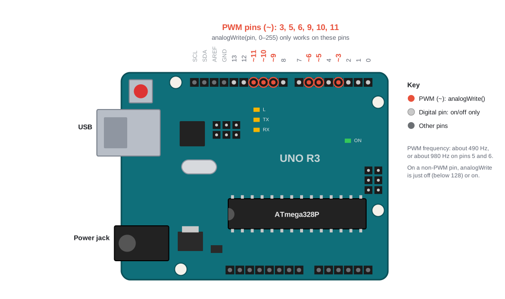
⚠️ The pin never outputs a voltage between 0 and 5 V. It switches between 0 V and 5 V; only the average lies in between. A multimeter usually shows the average, an oscilloscope shows the pin jumping.
Try it: PWM visualiser — drag the slider to see the waveform, duty cycle and average voltage; click pins to check which support PWM. · Open full screen ↗
A ramp is a fade
Ramping a pump up is the same code as fading an LED up. Exercise 2b brightens an LED in steps of 10 (about 0.2 V average) with a for loop:
/*
 * Exercise 2b: Brighten a red LED from 0 V to about 5 V (average) in steps of
 * about 0.2 V, then dim it back down, using for loops. Repeats forever.
 * Hardware: red LED + 220 Ω resistor from D10 (a PWM pin) to GND.
 */

const uint8_t  kRedPin  = 10;     // PWM (~) pin
const uint16_t kStepMs  = 500;    // time at each brightness (ms)
const int      kPwmStep = 10;     // 10 / 255 x 5 V ≈ 0.2 V (average) per step
const int      kTopPwm  = 255 - (255 % kPwmStep);   // largest multiple of the step: 250

void setup() {
  pinMode(kRedPin, OUTPUT);
}

void loop() {
  for (int pwm = 0; pwm <= kTopPwm; pwm += kPwmStep) {            // brighten
    analogWrite(kRedPin, pwm);
    delay(kStepMs);
  }
  for (int pwm = kTopPwm - kPwmStep; pwm > 0; pwm -= kPwmStep) {  // dim
    analogWrite(kRedPin, pwm);
    delay(kStepMs);
  }
}- Why
intand notuint8_t? Auint8_tholds only 0 to 255. A counter that steps past 255 would wrap round to a small number, and the loop could run forever. - Count in whole
analogWritevalues, not infloatvolts: 0.2 can’t be stored exactly, so small errors build up.
This version blocks: while the for loop runs, the Arduino does nothing else. For the pump that’s not acceptable, because the RES must still be watched during the ramp. Section 5 does the same ramp with millis(), as in Getting started with the Arduino.
Run it: Exercise 2b in the code runner — watch pwm climb in steps of 10, then fall again (try 4× speed). · Open full screen ↗
4. The L298N on the project board
An Arduino pin can’t drive a pump even with PWM: it can only supply 20 mA at 5 V. The board uses an L298N, a dual H-bridge driver. One of its two channels, channel B, drives the pump. It switches VPump onto the pump, under the control of three logic pins:
| L298N pin | Net | Arduino pin | Role |
|---|---|---|---|
| IN3 | InC | D3 (PWM) | Sets OUT3 high or low |
| IN4 | InD | D2 | Sets OUT4 high or low |
| EnB | Enable | D4 | Turns channel B on (HIGH) or off (LOW) |
| Vs | VPump | — | The supply the pump receives |
| Vss | +5V | — | The L298N’s logic supply |
How an H-bridge drives a motor
Each output (OUT3, OUT4) can be switched to the supply or to ground, so the pump can be driven either way round, or stopped:
| EnB | IN3 | IN4 | OUT3 | OUT4 | Pump |
|---|---|---|---|---|---|
| HIGH | HIGH | LOW | VPump | GND | Runs one way |
| HIGH | LOW | HIGH | GND | VPump | Runs the other way |
| HIGH | HIGH | HIGH | VPump | VPump | Brakes: both terminals joined |
| HIGH | LOW | LOW | GND | GND | Brakes: both terminals joined |
| LOW | any | any | off | off | Coasts: outputs disconnected |
The jumpers: choosing the drive type
JP1 and JP2 connect the pump terminals (J1: M1, M2) either to the L298N or straight to the supply:
| Jumper | Direct drive | Slow start (L298N) |
|---|---|---|
| JP2 → M1 | VPump | OUT4 |
| JP1 → M2 | GND (GNDS) | OUT3 |
Check the positions against the silkscreen on your board. In direct drive, M1 is the positive terminal. To run the pump the same way round through the L298N, OUT4 must be the positive side: IN4 HIGH, with IN3 LOW to drive.
PWM on IN3
EnB is on D4, which is not a PWM pin, so the PWM has to go on IN3 (D3, which is). With EnB HIGH and IN4 HIGH:
- IN3 LOW: OUT4 = VPump, OUT3 = GND: the pump is driven.
- IN3 HIGH: both outputs at VPump: the pump’s terminals are joined, and the current circulates through the bridge (brake).
So the drive is the time IN3 spends LOW. To drive the pump at a level from 0 to 255, write the inverse: analogWrite(3, 255 - level).
💡 If the pump’s direction doesn’t matter (or you swap its wires for L298N mode), hold IN4 LOW and write
analogWrite(3, level)directly. Moving Enable to a PWM pin in a future board revision would also allow the more common “PWM on enable” method.
Things to know about the L298N
- Voltage loss. The L298N uses bipolar transistors, which drop about 2 V in total at 1 A (more at higher current). At full drive the pump gets less than in direct drive.
- Current limit. 2 A continuous per channel. A slow start keeps the pump within it; a direct start through the L298N would not.
- Current sense. SENSE_A and SENSE_B go to ground through R1 (0.2 Ω). The voltage across R1 is \(0.2\,\Omega \times I\), so an oscilloscope across R1 shows the pump current: 1 A gives 0.2 V. It is the easiest way to see the inrush current, and to compare the two drive types.
- PWM whine. At about 490 Hz the pump may hum audibly while it ramps.
- Decoupling. C1 and C2 (100 nF) on +5V and VPump smooth the switching spikes.
5. Slow start
A slow start (soft start) raises the pump’s average voltage gradually, so the back-EMF can build as the pump speeds up and the current never jumps far above its running value.
- At start-up: ramp the drive from 0 to 100 % over a set time, e.g. 2 s.
- At a switch-over to a higher supply: first reduce the drive so the pump’s average voltage stays about the same, switch the supply, then ramp back up to 100 %. For example, running flat out on an 8 V RES and switching to a 12 V battery, drop the drive to \(255 \times 8/12 = 170\) (about 8 V average from 12 V), switch, then ramp.
- At a switch-over to a lower supply: no surge, so no ramp is needed.
The code
The ramp is non-blocking: loop() keeps checking the RES while the pump speeds up, and a switch-over during a ramp is handled straight away.
/*
 * RenewableSwitchOver board: supply switch-over with a slow-started pump.
 * Pins from the schematic: A0 = AnalogIn (trimmer wiper),
 *   D13 = renewableOn, D12 = batteryOn (both active-HIGH),
 *   D3 = InC (L298N IN3, PWM), D2 = InD (IN4), D4 = Enable (EnB).
 * Jumpers JP1/JP2 set to the L298N outputs.
 */

const uint8_t  kSensePin   = A0;
const uint8_t  kResOnPin   = 13;      // renewableOn
const uint8_t  kBatOnPin   = 12;      // batteryOn
const uint8_t  kIn3Pin     = 3;       // InC: a PWM pin
const uint8_t  kIn4Pin     = 2;       // InD
const uint8_t  kEnablePin  = 4;       // Enable (EnB)

const float    kRatio      = 0.300;   // fraction of the RES voltage at A0, measured at TP1
const float    kBatteryV   = 12.0;    // battery voltage (measure yours)
const float    kToBatteryV = 8.0;     // RES volts: switch to the battery below this ...
const float    kToResV     = 9.0;     // ... and back to the RES only above this
const float    kAdcVref    = 5.0;
const float    kAdcMax     = 1023.0;

const unsigned long kRampMs   = 2000; // time to reach full drive after a ramp starts
const unsigned long kSampleMs = 100;  // time between RES readings

bool          onBattery    = false;
uint8_t       level        = 0;       // pump drive: 0 (off) to 255 (full)
uint8_t       rampFrom     = 0;       // drive level when the current ramp started
unsigned long rampStartMs  = 0;
unsigned long lastSampleMs = 0;

// The RES voltage, from the A0 reading and the measured divider fraction.
float readResVolts() {
  return analogRead(kSensePin) * (kAdcVref / kAdcMax) / kRatio;
}

// Drive the pump at 'lvl' (0 to 255). IN4 is held HIGH, so IN3 LOW drives the
// pump (the same way round as direct drive) and IN3 HIGH doesn't: the drive is
// the time IN3 spends LOW, so write the inverse.
void setPump(uint8_t lvl) {
  level = lvl;
  analogWrite(kIn3Pin, 255 - lvl);
}

// Start a ramp from 'from' up to full drive.
void startRamp(uint8_t from) {
  setPump(from);
  rampFrom    = from;
  rampStartMs = millis();
}

// Move the ramp on. Called on every pass of loop(), so it never blocks.
void updateRamp(unsigned long now) {
  if (level == 255) return;                   // already at full drive
  unsigned long t = now - rampStartMs;        // time since the ramp started
  if (t >= kRampMs) {
    setPump(255);
  } else {
    setPump(rampFrom + (255UL - rampFrom) * t / kRampMs);
  }
}

// Change supply. If the new supply is higher, first cut the drive so the pump's
// average voltage stays about the same, then let it ramp back up.
void changeSupply(bool toBattery, float vRes) {
  float vOld = toBattery ? vRes : kBatteryV;
  float vNew = toBattery ? kBatteryV : vRes;
  if (vNew > vOld) {
    startRamp((uint8_t)(level * vOld / vNew));
  }
  // Make before break: diodes D1/D2 stop the supplies feeding each other.
  digitalWrite(toBattery ? kBatOnPin : kResOnPin, HIGH);
  digitalWrite(toBattery ? kResOnPin : kBatOnPin, LOW);
  onBattery = toBattery;
}

void setup() {
  pinMode(kResOnPin, OUTPUT);
  pinMode(kBatOnPin, OUTPUT);
  pinMode(kIn3Pin, OUTPUT);
  pinMode(kIn4Pin, OUTPUT);
  pinMode(kEnablePin, OUTPUT);

  digitalWrite(kIn4Pin, HIGH);        // sets the pump's direction
  setPump(0);                         // no drive yet
  digitalWrite(kEnablePin, HIGH);     // L298N channel B on

  onBattery = readResVolts() < kToBatteryV;
  digitalWrite(onBattery ? kBatOnPin : kResOnPin, HIGH);
  startRamp(0);                       // slow start from standstill
}

void loop() {
  unsigned long now = millis();

  // 1. Every 100 ms, read the RES and decide on the supply (with hysteresis).
  if (now - lastSampleMs >= kSampleMs) {
    lastSampleMs = now;
    float vRes = readResVolts();
    if (!onBattery && vRes < kToBatteryV) {
      changeSupply(true, vRes);       // RES clearly too low
    } else if (onBattery && vRes > kToResV) {
      changeSupply(false, vRes);      // RES clearly recovered
    }
  }

  // 2. On every pass, move the pump's ramp on.
  updateRamp(now);
}
How it works
setPump()is the only place that knows about the inverted PWM on IN3. The rest of the code thinks in drive levels, 0 to 255.startRamp()records where and when a ramp begins;updateRamp()works out the level from the time since then: \(\text{level} = \text{from} + (255 - \text{from}) \times t / T_{ramp}\). The255ULmakes the sum useunsigned longmaths, because \(255 \times 2000\) is too big for anint.changeSupply()compares the old and new supply voltages. Only a step up causes a surge, so only then is the drive cut before the switch.- Nothing blocks. Each pass of
loop()takes well under a millisecond, so the RES is checked every 100 ms even in the middle of a ramp.
Things to set for your hardware
kRatio(measured at TP1) andkBatteryV(measure the battery).kToBatteryVandkToResVfrom the pump’s minimum working voltage.kRampMs: longer means a smaller surge but a slower start. Measure the current across R1 with an oscilloscope and lengthen the ramp until the peak is close to the running current.
Advantages and disadvantages
| Advantages | Disadvantages |
|---|---|
| Low inrush current: the current rises with the back-EMF instead of jumping to \(V/R\) | More parts: an H-bridge driver (here the L298N), and the jumpers set correctly |
| Smooth switch-overs: the drive is matched to the new supply, so no surge | More code, and it must be non-blocking so monitoring continues |
| Keeps the RES stable: no surge to drag it below the threshold, so no false switch-overs | Voltage loss: about 2 V in the L298N, so the pump never gets the full supply |
| Gentler on the diodes, MOSFETs, battery, wiring and the pump; no water hammer | Slower to reach full flow: the pump takes the ramp time to get going |
| Keeps the L298N within its 2 A rating | PWM whine from the pump, and some heat in the L298N |
| Speed control for free: the same PWM can run the pump slower when less flow is needed | At very low duty cycles the pump may hum without turning |
6. Direct drive or slow start?
| Direct drive | Slow start | |
|---|---|---|
| Inrush at start-up | Full: \(V/R\), several times the running current | Small: rises with speed |
| Surge at a switch-over | Yes, whenever the supply steps up | No: drive matched, then ramped |
| Effect on the RES | Can sag it below the threshold and cause repeated switching | Stays stable |
| Voltage at the pump | VPump (minus the diode drop) | VPump minus about 2 V more (L298N) |
| Time to full flow | Immediate | The ramp time (e.g. 2 s) |
| Parts and code | Jumpers to direct; switching code only | L298N; ramp code with millis() |
| Speed control | None | Yes, with the same PWM |
For a renewable source that can’t supply large surges, slow start is the better choice: it protects the source, the switching parts and the pump, and the cost (a little voltage, and a second or two to reach full flow) is small. Direct drive suits a stiff supply such as the battery alone, or a pump that struggles to start at reduced voltage.
Key points
- A DC motor’s current is \(I = (V - E)/R\). At standstill \(E = 0\), so the inrush current is \(V/R\), often several times the running current. A sudden step up in supply voltage causes a surge too.
- Direct drive is simple and loses no extra voltage, but takes the full surge at every start and every switch-over to a higher supply.
- PWM sets an average voltage: \(V_{avg} = V_{supply} \times \text{value}/255\).
- On the board, the L298N drives the pump: EnB (D4) HIGH and IN4 (D2) HIGH, with PWM on IN3 (D3) written as
255 - level. JP1/JP2 choose direct or L298N drive. - A slow start ramps the drive up with non-blocking
millis()code, and cuts the drive before switching to a higher supply, keeping the current near its running value.
Knowledge check
Test yourself on this chapter. Answers are checked as you go; calculations with New numbers can be tried again with different values.
A PWM signal is on for 7.5 ms and off for 2.5 ms. What is its duty cycle, and the average voltage from a 5 V pin?
Period = 7.5 + 2.5 = 10 ms; duty = 7.5/10 = 75 %; V_avg = duty × 5 V = 3.75 V
What duty cycle and average voltage does analogWrite(pin, [191]{.kc-v data-k="v"}) give?
duty = 191/255 = 74.9 %; V_avg = 5 × 191/255 = 3.75 V
What analogWrite value gives an average of 1.5 V from a 5 V pin? (Round to a whole number.)
value = (255 / 5 V) × V, rounded to the nearest whole number.
value = (255 / 5) × 1.5 = 76.5 → 76
analogWrite uses bits, giving 2⁸ = levels, so its value runs from 0 to . It only works on the PWM pins marked ~.
What is PWM used for? Select all that apply.
Motor speed control
LED dimming
Audio signal generation
Reading an analogue sensor
That’s analogRead, the ADC, not PWM.
Why does an LED on a 50 % PWM signal look steadily dimmer rather than flickering?
It switches about 490 times a second, far too fast for the eye to follow, so we see the average
The LED’s voltage is really 2.5 V all the time
The pin is only ever at 5 V or 0 V; it’s the average that is 2.5 V.
The resistor smooths the pulses
LEDs can’t turn off quickly
The PWM pins on the Uno are ~3, ~5, ~6, ~, ~10 and ~. They run at about Hz, except pins 5 and 6 at about 980 Hz.
Adjust the on-time and off-time of a 5 V PWM signal to give a 75 % duty cycle with a 10 ms period.
Set the analogWrite value so the LED’s pin gives an average of 3 V (±0.05).
value = 255/5 × 3 = 153. The pin is only ever 5 V or 0 V; the dashed line is the average.
Complete the loop that brightens the LED from 0 to 250 in steps of 10.
for (int pwm = 0; pwm  kTopPwm; pwm  kPwmStep) {
  analogWrite(kRedPin, );
  delay(kOnMs);
}
Why is the loop counter an int rather than a uint8_t when testing pwm <= 255?
A uint8_t holds only 0–255, so 260 would wrap round to 4 and the loop would never end
analogWrite only accepts int
int is faster on the Arduino
uint8_t can’t be used in a for loop
A 12 V pump has a winding resistance of 2 Ω and runs at 0.8 A. Estimate its current at the moment it is switched on, and how many times its running current that is.
At standstill the back-EMF is zero, so only the winding resistance limits the current.
I_start = 12 / 2 = 6 A, which is 7.5 × the running current of 0.8 A.
The pump (winding resistance 2 Ω) is running from the RES at 8 V when the board switches it straight to the battery at 12 V. Roughly how big is the extra current surge?
ΔI ≈ (12 − 8) / 2 = 2 A, on top of the running current, until the pump speeds up.
The pump is at full drive (255) on a 8 V RES. Before switching to a 12 V battery, the slow-start code cuts the drive so the pump’s average voltage stays the same. To what level?
level = 255 × 8 / 12 = 170, i.e. 8 V average from the 12 V supply. Then it ramps back up to 255.
With EnB HIGH and IN4 HIGH, what happens when IN3 is LOW?
OUT4 is at VPump and OUT3 at ground, so the pump is driven (M1 positive, as in direct drive)
Both outputs are at VPump, so the pump brakes
That’s IN3 HIGH, the same as IN4.
The outputs are disconnected and the pump coasts
That’s EnB LOW.
The pump runs backwards at full speed
On the board, IN4 is held HIGH and the PWM goes on IN3, so the pump is driven while IN3 is LOW. Set the analogWrite value on IN3 so the pump gets 75 % drive (±1).
The drive is the time IN3 spends LOW, so write the inverse, analogWrite(3, 255 - level); 75 % drive is 191, written as 64.
Which are advantages of a slow start over direct drive? Select all that apply.
A much smaller inrush current at start-up
No surge to drag the RES below the threshold and cause false switch-overs
Keeps the L298N within its 2 A rating
The pump gets a higher voltage at full speed
The L298N drops about 2 V, so the pump gets less than in direct drive.
Fewer parts and less code
It needs the H-bridge and non-blocking ramp code.
Why is the slow-start ramp written with millis() rather than a for loop with delay()?
So loop() keeps reading the RES and can switch supplies during the ramp
Because delay() can’t be used with analogWrite
Because millis() makes the PWM frequency higher
Because a for loop can’t count past 255
An int counter can; the problem is that the loop blocks everything else.