Getting started with the Arduino
Chapter 2 · Introduction to microcontrollers
The microcontroller system in the project overview is an Arduino Uno. It reads the scaled RES voltage, decides which supply to use, drives the switching circuitry and starts the pump. This chapter is a quick introduction to the board and to writing programs for it, so that the following chapters can concentrate on the project.
Learning outcomes
By the end of this chapter you should be able to:
- Describe the Arduino Uno R3 and the electrical limits of its pins
- Set up the Arduino IDE and explain the
setup()/loop()structure of a sketch - Drive a digital output and size a current-limiting resistor for an LED
- Choose suitable data types and use named constants, loops, arrays and functions
- Distinguish blocking (
delay) from non-blocking (millis) timing
1. The microcontroller in a mechatronic system
A microcontroller (MCU) is the decision-making element of an embedded control system. It samples sensors, executes a control law in firmware, and commands actuators, usually through driver stages, because MCU pins can only supply a few milliamps.
| Inputs (sensors) | Typical interface | Outputs (actuators/displays) | Typical interface |
|---|---|---|---|
| Temperature (thermistor, LM35) | Analogue voltage → ADC | LEDs | Digital output / PWM |
| Humidity (DHT22) | Single-wire digital | Stepper motors | Step/direction to a driver (A4988) |
| Light (LDR, photodiode) | Analogue via divider | DC motors | PWM to an H-bridge (L298N) |
| Infrared (PIR, IR receiver) | Digital | Servos | 50 Hz PWM pulse width |
| Distance (HC-SR04 ultrasonic) | Digital pulse timing | LCD displays | I²C or parallel |
The project uses three of these patterns: an analogue voltage through a divider (the RES voltage on A0), digital outputs through driver transistors (the switching circuitry), and PWM to an H-bridge (the L298N pump driver).
2. Arduino Uno R3 hardware
The Uno R3 (the Elegoo board in the lab is a compatible clone) is built around the Microchip ATmega328P:
| Parameter | Value |
|---|---|
| Core | 8-bit AVR RISC, 16 MHz (≈ 16 MIPS) |
| Flash (program) / SRAM (variables) / EEPROM | 32 KB (0.5 KB used by the bootloader) / 2 KB / 1 KB |
| Digital I/O | 14 pins (D0–D13), 6 with PWM (~ 3, 5, 6, 9, 10, 11) |
| Analogue inputs | 6 (A0–A5), 10-bit ADC (0–1023) |
| Logic level | 5 V |
| Pin current | 20 mA recommended, 40 mA absolute maximum per pin; 200 mA total through VCC/GND |
| Supply input | USB 5 V, or 7–12 V on the barrel jack / Vin |
| Serial interfaces | UART (D0 RX / D1 TX, shared with USB), SPI (D10–D13 / ICSP), I²C (A4 SDA / A5 SCL) |
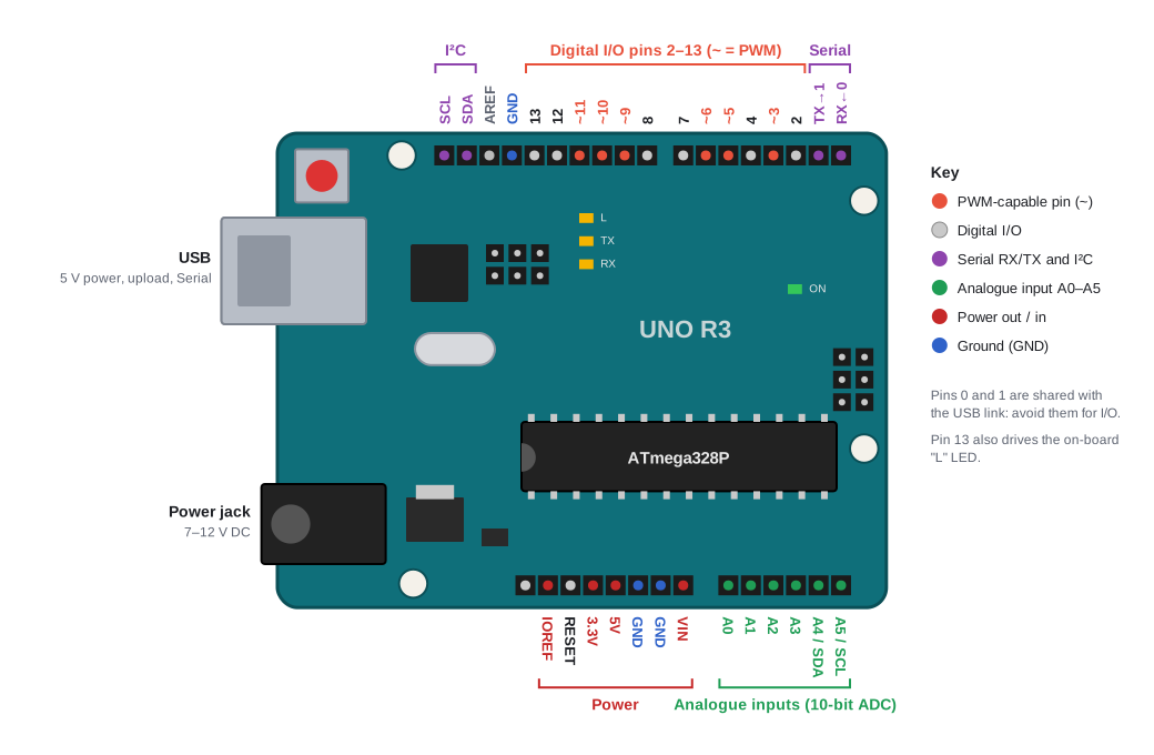
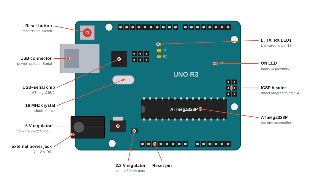
| Feature | Function |
|---|---|
| USB connector (with a USB–serial converter) | Powers the board, uploads firmware via the bootloader, carries Serial data |
| External power jack / Vin | 7–12 V input to the on-board 5 V linear regulator (see Voltage regulation) |
| 3.3 V regulator | Low-current (≈ 50 mA) 3.3 V output for 3.3 V sensors |
| 16 MHz crystal | Clock source; sets timing accuracy for millis(), serial baud rates and PWM |
| Reset button / pin | Restarts the program from setup() |
| D0/D1 (RX/TX) | Used by Serial and for uploading; avoid using them as general I/O |
The 20 mA pin limit is the reason the project never powers anything heavier than an LED straight from a pin: the supplies are switched through transistors and the pump through the L298N.
3. Toolchain and program structure
Install the Arduino IDE 2.x from https://www.arduino.cc/en/software.
Select the board: Tools › Board › Arduino AVR Boards › Arduino Uno.
Select the serial port: Tools › Port (COMx on Windows,
/dev/ttyACM0or/dev/cu.usbmodem…on Linux/macOS).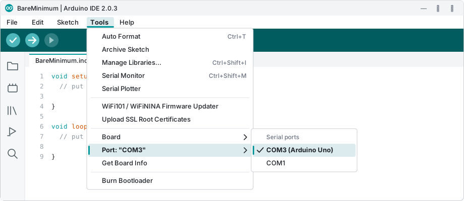
Selecting the serial port in the Tools menu Start from File › Examples › 01.Basics › BareMinimum.
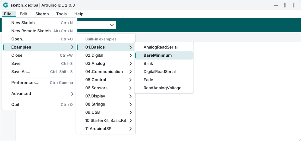
File › Examples › 01.Basics › BareMinimum
Verify compiles the sketch (C++ with the Arduino core library); Upload compiles it and transfers the program to the board. Every Arduino sketch has the same two functions:
void setup() {
  // put your setup code here, to run once:

}

void loop() {
  // put your main code here, to run repeatedly:

}setup()runs once, when the board powers up or is reset. Use it to configure pins (pinMode) and start serial communication (Serial.begin).loop()then runs over and over, forever, until the power is removed.
There is no operating system: loop() is a super-loop, and anything that blocks inside it (a long delay(), waiting on a sensor) stops every other task. Section 8 returns to this point, and it matters for the project: the Arduino has to keep watching the RES voltage while it ramps the pump up.
4. Prototyping on a breadboard
A solderless breadboard is a matrix of spring-contact clips:
- Terminal strips: each half-column of five holes (a–e, f–j) is one clip. The centre channel isolates the two halves, so a chip can straddle it.
- Power rails: continuous along the board’s length (on some full-size boards they are split at the midpoint). Top and bottom rails are independent.
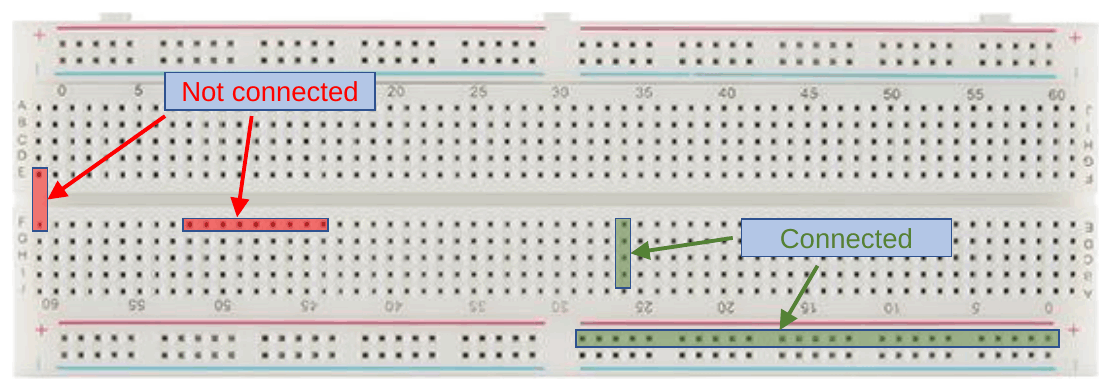
The clips are rated at roughly 1 A and add 10–50 mΩ per contact. That is fine for LEDs and sensors but rules breadboards out for motor currents: the project board puts the supply and pump connections on screw terminals.
Try it: Breadboard continuity lab — add wires and components, reveal the hidden strips, test continuity between any two holes, and check whether each component is placed correctly. · Open full screen ↗
5. Digital output and LEDs
pinMode(pin, OUTPUT) makes a pin an output; digitalWrite(pin, HIGH) drives it to ≈ 5 V and LOW to ≈ 0 V.
LEDs need a series resistor
The anode (+, long leg) of an LED must be at the higher potential, the cathode (−, short leg, flat edge on the lens) at the lower.
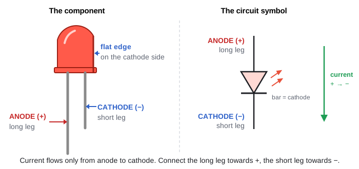
An LED is a diode: its current rises exponentially with voltage, so it cannot set its own current. Connected straight to a supply, the current is limited only by the supply’s internal resistance and the LED burns out. A series resistor sets the current. Above the knee of its curve the LED’s voltage is roughly its forward voltage \(V_f\), so:
\[R = \frac{V_s - V_f}{I_F}\]
From a 5 V pin, a red LED (\(V_f \approx 2\) V) at 15 mA needs \(R = (5 - 2)/0.015 = 200\ \Omega\) → use the next standard value up, 220 Ω. Always round up, and check the resistor’s power, \(P = I^2R\).
The project board uses the same idea for its two supply indicators (D3 “Battery ON” and D4 “Renew ON”, each with a 360 Ω resistor, see Switching circuitry).
LED circuit explorer — choose a supply and LED colour, slide through the standard resistor values and watch the current. Pick a resistor that is too small and the LED burns out. · Open full screen ↗
Try these: (if the LED burns out, move the slider to a larger resistor first, then press Replace the LED)
- With the 9 V battery and a red LED, find the smallest standard resistor that keeps the current at or below 20 mA.
- Slide all the way to no resistor. What happens, and why?
- Switch to a blue LED. Why does the smallest safe resistor change?
- At the resistor you found in task 1, how much power does the resistor dissipate? Is a standard ¼ W resistor enough?
Answers
- 390 Ω. Exactly 20 mA needs \(R = (9 - 2.0)/0.020 = 350\ \Omega\), which is not a standard value. The next E12 value up is 390 Ω, giving \((9 - 2.0)/390 = 17.9\ \text{mA}\).
- With no resistor, only the battery’s small internal resistance limits the current, so it tries to reach amps, far past the 30 mA maximum, and the LED burns out.
- A blue LED has a higher forward voltage (3.2 V), so the resistor has less voltage across it: \((9 - 3.2)/0.020 = 290\ \Omega\), so the smallest safe standard value is 330 Ω.
- \(P = V_R^2/R = 7^2/390 \approx 126\ \text{mW}\): about half of a ¼ W (250 mW) rating, which is acceptable.
Example 1a — blink an LED
/*
 * Example 1a: Blink an LED at 1 Hz (0.5 s on, 0.5 s off).
 * Hardware: red LED + 220 Ω resistor from D13 to GND.
 */

const uint8_t  kLedPin       = 13;    // the LED is wired to digital pin 13
const uint16_t kHalfPeriodMs = 500;   // on time = off time, in milliseconds

// setup() runs once, when the board powers up or is reset.
void setup() {
  pinMode(kLedPin, OUTPUT);           // pin 13 drives (outputs to) the LED
}

// loop() runs over and over, forever.
void loop() {
  digitalWrite(kLedPin, HIGH);        // 5 V on pin 13: LED on
  delay(kHalfPeriodMs);               // wait 500 ms
  digitalWrite(kLedPin, LOW);         // 0 V on pin 13: LED off
  delay(kHalfPeriodMs);               // wait 500 ms, then loop() starts again
}constmeans the value can never change while the program runs. If you accidentally writekLedPin = 12;later, the compiler stops with an error.uint8_tis a whole number that uses 1 byte and holds 0 to 255: plenty for a pin number.uint16_tuses 2 bytes, 0 to 65 535, enough for delays up to about 65 s.- The
kat the start of a name is a convention for constant: a fixed value set at the top of the file.
Pin 13 also drives the on-board “L” LED. On the project board, pin 13 is renewableOn, so the “L” LED lights whenever the RES is switched in.
Run it: Example 1a in the code runner — the active line is highlighted as the LED blinks. · Open full screen ↗
6. Data types and named constants
On an 8-bit AVR, type sizes differ from a desktop PC, and with only 2 KB of SRAM they matter:
| Type | Size | Range | Typical use |
|---|---|---|---|
bool |
1 byte | true / false |
Flags and states (e.g. onBattery) |
uint8_t |
1 byte | 0–255 | Pin numbers, PWM duty, small counters |
int / int16_t |
2 bytes | −32 768 to 32 767 | General integers, analogRead() results |
uint16_t |
2 bytes | 0–65 535 | Short delays in ms |
long / int32_t |
4 bytes | ±2.1 × 10⁹ | Large counts and intermediate sums |
unsigned long |
4 bytes | 0–4.29 × 10⁹ | Timestamps from millis() |
float |
4 bytes | ~7 significant digits | Measured voltages, scaled values |
Good practice:
- Declare fixed values as
const. This documents intent and makes a hardware change (e.g. moving an LED to another pin) a one-line edit. - Use the smallest type that fits the range, and
unsigned longfor anything compared withmillis(). - Avoid the Arduino
Stringclass in long-running firmware: repeated concatenation fragments the 2 KB heap. Use string literals or theF()macro:Serial.println(F("Source: RES"));.
7. Loops, arrays and functions
Example 1b — varying the on-time with a for loop
Repeating the same four lines for each delay is error-prone. Store the values in an array and loop through it:
/*
 * Example 1b: Blink an LED with on-times stepping from 0.1 s to 1 s.
 * Hardware: red LED + 220 Ω resistor from D13 to GND.
 */

const uint8_t  kLedPin      = 13;                          // LED pin
const uint16_t kOffMs       = 500;                         // off time after each blink (ms)
const uint16_t kOnTimesMs[] = {100, 250, 500, 750, 1000};  // on time for each blink (ms)

// Number of values in the array = total bytes / bytes per value = 5.
const size_t   kNumSteps    = sizeof(kOnTimesMs) / sizeof(kOnTimesMs[0]);

void setup() {
  pinMode(kLedPin, OUTPUT);
}

void loop() {
  // i takes the values 0, 1, 2, 3, 4: one pass for each value in the array.
  for (size_t i = 0; i < kNumSteps; ++i) {
    digitalWrite(kLedPin, HIGH);         // LED on
    delay(kOnTimesMs[i]);                // stay on for the i-th on time
    digitalWrite(kLedPin, LOW);          // LED off
    delay(kOffMs);
  }
}
for (size_t i = 0; i < kNumSteps; ++i): startiat 0, keep looping whilei < kNumSteps, add 1 after each pass.sizeofgives a size in bytes, worked out by the compiler. The whole array is 5 × 2 = 10 bytes and one value is 2 bytes, sokNumSteps= 10 ÷ 2 = 5. Add a sixth on-time and the count updates by itself.
Run it: Example 1b in the code runner — watch i step through the array and the on-time grow. · Open full screen ↗
Exercise 1c — three LEDs, with a struct, a table and a function
Task: blink a red LED 2 times, then a green LED 3 times, then a blue LED 4 times, each blink 0.5 s on and 0.5 s off, and repeat.
Written out with digitalWrite() and delay(), those nine blinks take 36 lines. Three tools make it short and easy to change:
- a
struct(BlinkStep) that bundles the two facts about each stage: which pin, and how many blinks; - a table (
kSequence) listing the stages in order; - a function (
blink) that blinks any LED any number of times.
/*
 * Exercise 1c: red 2 times, green 3 times, blue 4 times, each blink
 * 0.5 s on and 0.5 s off, using a struct, a table and a function.
 * Hardware: each LED in series with a 220 Ω resistor to GND.
 */

const uint8_t  kRedPin       = 13;
const uint8_t  kGreenPin     = 12;
const uint8_t  kBluePin      = 11;
const uint16_t kHalfPeriodMs = 500;   // time on, and time off, for each blink (ms)

// Each BlinkStep describes one stage: which pin, and how many blinks.
struct BlinkStep {
  uint8_t pin;
  uint8_t count;
};

// The sequence as a table. To change the order, a pin or a count, edit this only.
const BlinkStep kSequence[] = {
  {kRedPin,   2},
  {kGreenPin, 3},
  {kBluePin,  4},
};

// Blink one LED 'count' times.
void blink(uint8_t pin, uint8_t count, uint16_t halfPeriodMs) {
  for (uint8_t i = 1; i <= count; ++i) {
    digitalWrite(pin, HIGH);
    delay(halfPeriodMs);
    digitalWrite(pin, LOW);
    delay(halfPeriodMs);
  }
}

void setup() {
  for (const BlinkStep& step : kSequence) {   // every row of the table
    pinMode(step.pin, OUTPUT);
    digitalWrite(step.pin, LOW);              // start with the LED off
  }
}

void loop() {
  for (const BlinkStep& step : kSequence) {
    blink(step.pin, step.count, kHalfPeriodMs);
  }
}| Pass | step is |
step.pin |
step.count |
Call made |
|---|---|---|---|---|
| 1 | row 0 | 13 | 2 | blink(13, 2, 500): red blinks twice |
| 2 | row 1 | 12 | 3 | blink(12, 3, 500): green blinks 3 times |
| 3 | row 2 | 11 | 4 | blink(11, 4, 500): blue blinks 4 times |
- Read the
forline as “for each row inkSequence, call itstep”. The&meanssteplooks at the row in the table instead of copying it;constmeans the loop can read the table but not change it. - To make green blink 5 times, change one number in the table. To add a fourth LED, add one row.
blink()andloop()don’t change.
The project code uses the same habits: named constants for every pin and threshold, and small functions such as useBattery() and startRamp() so that loop() reads like the specification.
Run it: Exercise 1c in the code runner — press Step repeatedly: the Variables panel shows step.pin and step.count change as each row of the table is read. · Open full screen ↗
8. Blocking vs non-blocking timing
delay() halts the CPU. During the Exercise 1c sequence (9 blinks, about 9 s) the Arduino can do nothing else. That is unacceptable once it also has to monitor the RES voltage and react to it. The standard alternative is to compare elapsed time from millis() (milliseconds since reset) and act only when an interval has passed:
/*
 * Non-blocking blink: the LED toggles every 500 ms while loop() stays free
 * to run other tasks (e.g. reading the RES voltage) on every pass.
 */

const uint8_t       kLedPin     = 13;
const unsigned long kIntervalMs = 500;   // time between LED changes (ms)

unsigned long lastToggleMs = 0;          // millis() time of the last LED change
bool          ledOn        = false;      // remembers whether the LED is on

void setup() {
  pinMode(kLedPin, OUTPUT);
}

void loop() {
  const unsigned long now = millis();    // ms since the board started
  if (now - lastToggleMs >= kIntervalMs) {   // subtraction form is overflow-safe
    lastToggleMs = now;
    ledOn = !ledOn;                      // flip the state
    digitalWrite(kLedPin, ledOn ? HIGH : LOW);
  }

  // Other tasks run here every pass, e.g. checking the RES voltage.
}
ledOn ? HIGH : LOWis the ternary operator: a one-lineif ... else.millis()wraps around after about 49.7 days. Writing the test asnow - lastToggleMs >= intervalwithunsigned longarithmetic stays correct across the wrap.
The pump’s slow start in Pump drive type uses exactly this pattern, so the Arduino keeps checking the RES while the pump speeds up.
Run it: the non-blocking blink in the code runner — see loop() pass many times between LED toggles while millis() advances. · Open full screen ↗
Key points
- ATmega328P pins: 5 V logic, 20 mA recommended per pin, 200 mA total. Use driver stages (transistors, an H-bridge) for anything larger.
- Every sketch has
setup()(runs once) andloop()(runs forever). - An LED’s current must be set by a series resistor: \(R = (V_s - V_f)/I_F\), rounded up to a standard value.
- With 2 KB of SRAM, choose types deliberately and use
constfor fixed values. - Named constants, tables and functions make hardware changes one-line edits.
delay()blocks the super-loop. Usemillis()timing whenever the Arduino must do more than one thing at once.
Knowledge check
Test yourself on this chapter. Answers are checked as you go; calculations with New numbers can be tried again with different values.
Which statements about a solderless breadboard are true? Select all that apply.
Each half-column of five holes (a–e or f–j) is one connected clip
The centre channel isolates the two halves, so a DIP IC can straddle it
The power rails run along the board’s length
It is fine for motor currents of several amps
The clips are rated at roughly 1 A; move power circuits to screw terminals or a soldered board.
An LED’s anode is the leg and must be at the potential; the cathode has the flat edge on the lens.
Why can’t an LED be connected straight across a 9 V battery?
Its current rises exponentially with voltage, so nothing but the battery’s internal resistance limits it, and it burns out
A series resistor adds a linear element that sets the current.
LEDs only work on AC
9 V is too low to light an LED
The LED would light, but dimly
An LED with \(V_f\) = 2 V is to run at 20 mA from a 9 V supply. What series resistance gives exactly that current?
\(R = \dfrac{V_s - V_f}{I_F}\), with the current in amps.
R = (9 − 2) / 0.02 A = 350 Ω. Then round up to the next standard (E12) value.
Exactly 20 mA from 9 V through a red LED (\(V_f\) = 2.0 V) needs 350 Ω, which isn’t a standard value. Which E12 resistor should you fit?
390 Ω
Round up, giving 17.9 mA, safely under the 20 mA rating even with a 5 % low resistor.
330 Ω
That gives 21.2 mA, over the rating; the LED runs hot and wears out sooner.
270 Ω
25.9 mA, well over the rating.
No resistor
The LED would burn out.
A 390 Ω resistor carries 17.9 mA. How much power does it dissipate?
P = I²R = (0.0179)² × 390 = 125 mW, which you compare with the resistor’s rating (¼ W = 250 mW), allowing 50 % derating.
On the Arduino Uno, each I/O pin should carry at most mA (recommended), with an absolute maximum of mA. The ATmega328P has only KB of SRAM for variables. The PWM pins, marked ~, are 3, 5, 6, 9, 10 and .
Complete the blink sketch so the LED on pin 13 flashes at 1 Hz.
const uint8_t  kLedPin       = 13;
const uint16_t kHalfPeriodMs = ;

void () {
  pinMode(kLedPin, );
}

void loop() {
  digitalWrite(kLedPin, );
  delay(kHalfPeriodMs);
  digitalWrite(kLedPin, );
  delay(kHalfPeriodMs);
}
1 Hz means one full on–off cycle per second, so 500 ms on and 500 ms off. setup() runs once; loop() runs forever.
Why is the pin number declared as const uint8_t rather than plain int?
const stops it being changed by mistake, and uint8_t uses 1 byte instead of 2, which matters with only 2 KB of SRAM
int can’t hold the number 13
uint8_t makes the pin switch faster
Arduino requires all pin numbers to be const
Which data type should hold a timestamp from millis()?
unsigned long
It holds 0 to about 4.29 × 10⁹, and its arithmetic stays correct when millis() wraps round after about 49.7 days.
int
An int overflows after 32.8 seconds’ worth of milliseconds.
uint8_t
float
An array holds 5 values of type uint16_t. What do sizeof(array) and sizeof(array) / sizeof(array[0]) give?
Each uint16_t is 2 bytes, so the array is 5 × 2 = 10 bytes, and 10 ÷ 2 = 5 values.
Complete the non-blocking blink, which toggles the LED every 500 ms without stopping loop().
const unsigned long kIntervalMs = 500;
unsigned long lastToggleMs = 0;
bool ledOn = false;

void loop() {
  const unsigned long now = ;
  if (now -  >= kIntervalMs) {
    lastToggleMs = now;
    ledOn = ;
    digitalWrite(13, ledOn ? HIGH : LOW);
  }
}
Writing the test as now - lastToggleMs >= interval stays correct when millis() wraps round; now >= lastToggleMs + interval does not.
A red LED (\(V_f\) = 2.0 V) runs from a 9 V battery. Choose the series resistor so the LED current is between 15 and 20 mA, and check the resistor’s power stays well inside a ¼ W (250 mW) rating.
\(R = (V_s - V_f)/I\): 350–470 Ω gives 15–20 mA. In practice you’d fit the standard 390 Ω (17.9 mA, about 125 mW).